


Patient information: uses, side effects, how to take - Ameluz
Storage shelf with control unit (touchscreen monitor)
Mobile frame and lamp base (include support rail, castors and power supply)
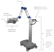
Figure 3: BF-RhodoLED® main components. (The appearance of devices from batches 001 to 003 slightly differs.)
The swivel range to the left and right of the vertical rail is +/- 24°. The lamp head can be adjusted horizontally and vertically and tilted sideways. The scissor arm with internal gas springs allows seamless adjustment of the lamp head to any position.
5 Eye Protection
In order to avoid eye irritation, glare or injury, protective eye equipment must be used by patient, healthcare providers and any person present during the illumination period. Do not stare into the light source! The operator and other persons present must wear protective glasses with a visible light transmission (VLT) of approximately 10%. The patient must wear eye protection such as disposable eye protection pads or eye caps with an optical density for visible light of 6 or higher. Both options are effective and comfortable for use during treatment.
Note: Eyewear is not part of the medical device. Please carefully read any accompanying usage information before using any eye protection.

In order to avoid eye irritation, glare or injury, protective eye equipment must be used by patient, healthcare providers and any person present during the illumination period.
6 BF-RhodoLED® PDT Summarized Step-by-Step Instructions
These instructions should be used in conjunction with detailed operating instructions below (chapter 7). The section titles and numbers listed next to the instruction refer to the detailed instructions and/or descriptions that correspond with each step.
Note: Every user of the BF-RhodoLED® has to be trained in operating the device. The initial training is provided by Biofrontera during set-up of the BF-RhodoLED®. Recurrent training is not mandatory but can be provided by Biofrontera employees. Before treating a patient with Ameluz, please ensure that BF-RhodoLED® is in good working order.
STEP 1)
Plug in lamp.
STEP 2)
Turn on the lamp and wait for home screen to appear (see chapter 7.3)
STEP 3)
Check the proper functioning of the BF-RhodoLED®.
STEP 4)
Treat the affected skin area: Application, incubation and removal of the topical medication following the USPI of Ameluz®.
STEP 5)
Position patient comfortably and place protective eyewear on patient (see chapter 5).
STEP 6)
Position the lamp and adjust the lamp head over the skin area to be treated (distance 5-8 cm) (see chapter 7.5.1).
STEP 7)
Put on protective eyewear and make sure anyone remaining in the treatment room also wears protective eyewear (see chapter 5).
STEP 8)
Start treatment by pressing "Treatment" on the home screen, press "Start" on the treatment screen, and press "Start" once again in the profile screen. The illumination period of 10 minutes begins (see chapter 7.5.3).
Remind the patient to remain still throughout the illumination period.
If sound tone during treatment is activated, explain the beep sequence to the patient.
If the patient needs a break, press "Break" on the profile standard screen. To resume treatment, press "Start" on the profile standard screen (see chapter 7.5.3).
To abort the illumination, press "Stop" on the profile standard screen.
Adjust fan speed as needed by patient by pressing plus or minus 1% or 10% on the profile standard screen.
Stay with the patient at all times during the illumination period.
STEP 9)
At the end of the illumination period, remove patient's protective eyewear and follow further instructions in the Ameluz® USPI.
7 Detailed Operating Instructions
Note: Every user of the BF-RhodoLED® has to be trained in operating the device. The initial training is provided by Biofrontera during set-up of the BF-RhodoLED®. Recurrent training is not mandatory but can be provided by Biofrontera employees. The device must be protected against unauthorized use.
In order to avoid eye irritation, glare or injury, protective eye equipment must be used by patient, healthcare providers and any person present during the illumination period.
7.1 Transport of the lamp
The transportation of the lamp shall be done when the scissor arm is completely folded. During transportation one hand shall hold on to the support rail or storage shelf while the other hand holds the scissor arm (Figure 4).
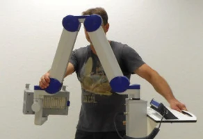
Figure 4: Transport of the lamp. (The appearance of devices from batches 001 to 003 slightly differs.)
7.2 Movement area of the scissor arm and the lamp head
The scissor arm has a swivel range of +/- 24 degrees to the left and right. The swivel range is limited by a pin at the connection between scissor arm/ support rail and scissor arm/ lamp head (Figure 5).
The lamp head can be adjusted horizontally and vertically and tilted sideways, as it has a swivel range of +/- 90 degrees in all three dimensions.
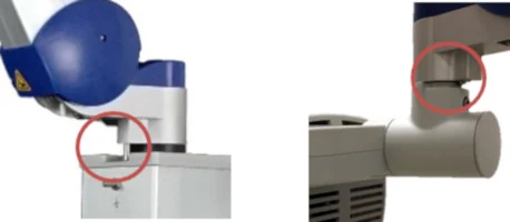
Figure 5: Limiting pins of the scissor arm and the lamp head. (The appearance of devices from batches 001 to 003 slightly differs. Appearance and location of the labels remain unaltered.)
7.3 Turning the Lamp On or Off
Note: Before turning on the lamp, the power cord must be plugged in. After connecting, the lamp can be turned on and used following the instructions below.
The on-off switch is located on the left side of the touchscreen monitor, close to its spiral cord. With the lamp plugged in, press the button to start the device.
Important: This push button can also be used to turn the lamp off. Switching off the lamp can also be done by pressing the switch off  button on the touchscreen (see chapter 7.4.2 "Home Screen").
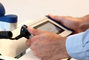
Figure 6 : Touchscreen monitor
Note : The blue LED of the push button indicates that the device is in stand-by mode.
7.4 Touchscreen Monitor and Menu
When using the touchscreen, please firmly press the center of the buttons shown on the screen to ensure it is read correctly by the software. Do not press too quickly, the input may not be read by the software. The touchscreen can be used while wearing commercially available examination gloves.
7.4.1 Start Screen
The Biofrontera corporate logo and software version are displayed during the LED lamp operating system start-up (Figure 7). The operating system takes approximately 30 seconds to load.
Figure 7 : Start screen
7.4.2 Home Screen
The home screen appears after the operating system has loaded. From the home screen you can select "Treatment", "Settings" or "Service" (Figure 8). In the "Treatment" menu only one treatment profile "profile standard" is available. The illumination time and light intensity of this program are fixed (see 7.5.3 for further information). The "Settings" menu allows adjustment of language, time, date, audio signals and power saving settings (see 7.6 for further information). The "Service" menu may only be accessed by authorized personnel. You can turn the LED lamp off by pressing the button.
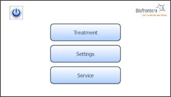
Figure 8 : Home screen
7.5 Conducting a Treatment
Prior to treating a patient with Ameluz please ensure that BF-RhodoLED® is in good working order. Before starting a treatment, make sure the lamp is set-up in accordance with the operating instructions described in the following sections.
7.5.1 Distance Indicator
Position the lamp head over the skin area to be treated at a distance of 5-8 cm. Use the adjustable distance indicator and graduated scale bar to help measure and aid in achieving the correct distance (Figure 9).
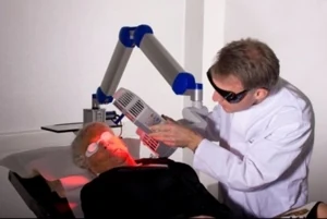
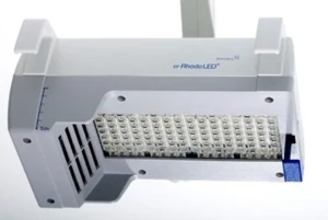
Figure 9 : Positioning of the lamp head to the treated skin area
7.5.2 Adjustment Light
To further aid positioning, use the adjustment light. On the touchscreen, press the following buttons in sequence (starting in the home screen): "Treatment" (Figure 8), "Adjust" (Figure 10) and "Start Adjustment" (Figure 11). The adjustment light shows what the field of illumination will be during treatment but at a lower intensity (6x16 cm, approx. 2.4 x 6.3 inches). When finished, press "Stop adjustment" and then "Back" (Figure 11) to return to the treatment menu (Figure 10).
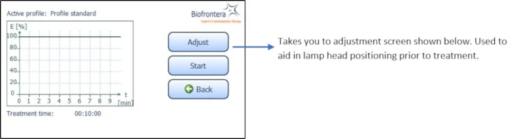
Figure 10 : Treatment menu
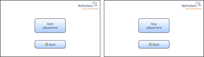
Figure 11 : Start and Stop adjustment
7.5.3 Treatment Menu
Press treatment to enter the treatment menu (Figure 8). The standard illumination profile is depicted in a graph in the treatment menu. The x- and y-axis specify the treatment duration and light intensity respectively (Figure 12).
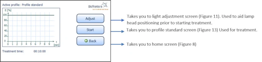
Figure 12 : Treatment menu
In the treatment menu (Figure 12), press the "Start" button to access the profile standard screen.
7.5.4 Profile Standard Menu
In the profile screen menu, press "Start" to begin treatment (Figure 13). You can interrupt the treatment at any time by pressing the "Break" button. Press the "Start" button to resume the treatment. Abort the current treatment by pressing the "Stop" button.
If you press "Stop" prior to the end of the total treatment time, 10 minutes, the clock will reset and any interim treatment time will be not be saved.
After pressing "Stop" or upon completion of the full 10 minute treatment the software will automatically return you to the treatment menu.
The remaining treatment time is displayed to the right of the graph and the red vertical line within the graph indicates the time that has elapsed.
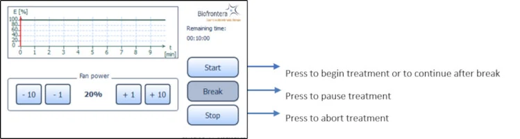
Figure 13 : Profile standard
7.5.5 Audio Signals during Treatment
During treatment the patient will hear audio signals, 1 beep indicating 25 %, 2 beeps indicating 50 % and 3 beeps indicating 75 % of the PDT is completed, and upon treatment completion the lamp will stop the illumination and 4 beeps will be heard (see also chapter 7.6.2).
7.5.6 Patient fan
You can control the speed of the patient fan both before and during treatment with the plus and minus buttons, in increments of 1 % or 10 %. The patient fan continues to run when the treatment is paused ("Break"). The fan can be stopped by pressing "Stop," but be aware the treatment will also be aborted and any elapsed treatment time will not be saved.
7.6 Settings Menu
The settings menu is invoked (Figure 14) by pressing the "Settings" button in the home screen view (see Figure 12).
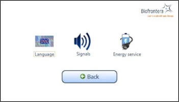
Figure 14: Settings menu
You can configure the following parameters in this menu:
Language
Signals
Energy service (Power management)
Switch back to the home screen menu via the "Back" button.
7.6.1 Language Settings
Select a language by tapping on the desired language. Use the arrow keys to scroll through the list. Confirm the selected language with the "OK" button (Figure 15). Switch back to the settings menu without saving changes by pressing the "Back" button instead of "OK".
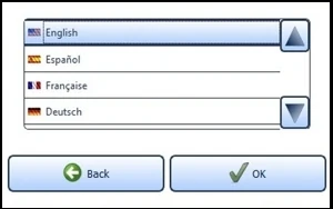
Figure 15: Language setting
7.6.2 Sound Settings
Activate and deactivate the audio signals for typing, warnings and sounds during the treatment. To do this, select the desired fields. A check mark means the sound is on.
Confirm with the "OK" button (Figure 16) to save your settings or close the menu via the "Back" button to discard the setting.
If "Turn off sound" is activated, all signal tones are switched off.
Important Note: Warning sounds will be emitted if an error occurs during operation of the lamp.
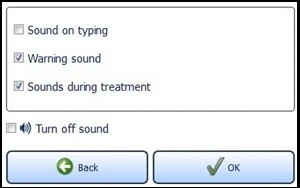
Figure 16 : Sound setting
7.6.3 Energy Service (Power Management)
Providing the standby function is not manually deactivated via the check box "Never turn off lamp automatically" located near the bottom of the screen, the lamp will turn off after 10 minutes of non-use (Figure 17). You can change this time span in the menu "Energy service" via the plus and minus buttons. The settings are confirmed with the "OK" button and rejected with the "Back" button. In both cases you will return to the settings menu.
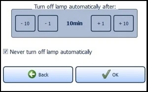
Figure 17: Energy management
If the configured time expires, a request appears for 10 seconds asking if you wish to prevent shut down. The LED lamp turns off automatically afterwards.
7.7 Service Menu
Authorization is required to access the service menu. Only authorized personnel can access the service menu.
8 Error Messages
The BF-RhodoLED® has an integrated monitoring function. In the event of a malfunction, an error message will appear in the message display. Possible error messages are set out in the table below.
Error message
Possible causes
Measures
Lamp overheated!
The temperature of the surrounding environment is too high.
The ventilators or ventilator slots are blocked.
The air inlets or outlets are adversely affected.
Wait until the standard temperature has been reached.
Check the ventilator and test the air inlets and outlets. Remove any visible foreign objects which may be present.
In case of continuing impairment of cooling please contact your local sales representative or Biofrontera.
Lamp error!
Please inform your supplier.
Some of the LEDs have failed.
Further treatments may be carried out. However, please contact your local sales representative or Biofrontera immediately.
Communication error!
Cable break in the touchscreen monitor spiral cord.
Poor contact between the touchscreen monitor connection plug and the conduit box.
Confirm the communication error. Treatments can be continued in the treatment menu by pressing the "Start" button.
Please contact your local sales representative or Biofrontera.
Lamp not calibrated!
The lamp is not calibrated.
Improper calibration.
The lamp has to be calibrated. Please contact your local sales representative or Biofrontera immediately.
Fehler-Nr.: 0084 Please inform your supplier.
A temperature sensor has failed.
The lamp head has to be repaired. Please contact your local sales representative or Biofrontera.
Firmware of light head is faulty or missing!
Please inform your supplier.
An Update of the firmware has to be performed.
An update of the firmware has to be performed. Please contact your local sales representative or Biofrontera.
If your LED lamp no longer functions properly for some unknown reason, proceed as follows:
Unplug the power supply for half a minute and then plug back into the outlet (This action prompts a software reboot).
Turn the lamp back on using the touchscreen monitor and verify functionality.
Should the problem persist, please contact your sales representative or Biofrontera. The lamp may not be used until the problem has been rectified.
For all other malfunctions and difficulties with operation please contact your sales representative or Biofrontera. You will find the contact details on page 2.
9 Servicing
Servicing may only be performed by Biofrontera-authorized personnel. If servicing is done by third parties, BF-RhodoLED® warranty is void and Biofrontera cannot be held responsible for potential malfunctions or damages of the device. It is recommended to have the lamp serviced after two years.
During service, the gas springs (gas pressure springs and gas traction springs) in the scissor arm as well as the general safety condition of the BF-RhodoLED® are checked.
Contact your sales representative or Biofrontera to schedule all service appointments.
10 Maintenance and Cleaning
The device may under no circumstances be cleaned with aggressive cleaning agents or solvents (e.g. acetone or highly concentrated ethanol), as these promote wear and tear of the surface (paint coating), safety signs and graduated scale bar as well as the logo. Please avoid allowing any penetration of liquids into the lamp; BF-RhodoLED® is not waterproof and the electronics inside may be damaged.
Always unplug the lamp prior to cleaning and please observe the following cleaning practices:
Daily:
Wipe the plexiglass screen located on the bottom of the lamp head with a damp soft cloth (e. g. a microfiber cloth).
Weekly:
Wipe the entire lamp. Do not use a very wet or dripping cleaning cloth. The unit is not waterproof, and damage could occur. Weekly cleaning can be carried out using a damp cloth. If disinfection of the device is desired, a mild disinfecting agent can be used. Most commercially available products, which are suitable for plastics, should be compatible with BF-RhodoLED®. A known exception is the agent "Incidin PlusTM" (active ingredient: Glucoprotamine) which can cause corrosion of the lamp head surfaces.
Before using a disinfection agent, always refer to its manual to check for compatibility with plastic surfaces, especially with Plexiglas.
Note: If you notice any deterioration of a surface of BF-RhodoLED after using a disinfectant, please stop further use and contact Biofrontera.
Please observe the following checks:
Monthly:
Check lamp for obvious visible damage such as damaged cables, worn off labeling, cracks on the lamp housing, etc. Do not use a damaged device for treatment and please inform your supplier.
11 Disposal Instructions
Follow all local and governmental disposal laws and regulations when disposing of the BF-RhodoLED®.
12 Technical Data
12.1 Electrical connectors
Power supply unit:
Primary wide-range input 100-240 VAC
Secondary safety extra-low voltage output 48 VDC
Secondary standby voltage output 5 VDC
Mother board for voltage management and control:
Supply voltage input 48 VDC
Standby voltage input 5 VDC plus Standby contact
RS485 interface
Output supply voltage HMI board 24 VDC
4 x ports LED board 8-pin (2 x LED circuits, temperature (3-pin))
4 x connector ventilator (2-pin)
LED board:
2 x ports mother board 8-pin (2 x LED circuits, temperature (3-pin))
Human Machine Interface (HMI) for operation:
Supply voltage input 24 VDC
RS485 interface
12.2 Specification
Type
BF-RhodoLED®
Medical device class III; Device of protection class 1
Certification
UL certified
Manual is valid for Software Version No.
1.6_US_CAN or lower
(for your current software version, see start screen 7.4.1)
Service life of the lamp
Approx. 4 years
Shelf life
1.5 years
Number of LEDs
128
Typical peak wavelength
635 nm ± 5 nm
Light dose (6 cm distance, 10 min)
Approx. 37 J/ cm2
Typical irradiance
61 mW/cm2 +/- 15 %
Max irradiance
77 mW/cm2 +/- 15 % (at 5 cm treatment distance)
Illuminated area
An area of 8x18 (approx. 3.1 x 7.1 inches) cm is illuminated. The effective treatment area is 6x16 cm (approx. 2.4 x 6.3 inches).
Max. deviation of the intensity over the treatment area
Approx. 15 %
Transport and storage conditions
Temperature: -30°C to +60°C (-22°F to +140°F)
Atmospheric pressure: 500 hPa - 1060 hPa
Relative humidity: 10% - 90%, non-condensing
Operating conditions
Temperature: 0°C to +40°C (32°F to +104°F)
Atmospheric pressure: 700 hPa - 1060 hPa
Operational altitude: ≤ 2000 m above NN
Relative humidity: 10% - 90%, non-condensing
This PDT lamp is suitable for continuous operation.
Operating voltage
120-240 VAC, 50/60 Hz
Output voltage
48 VDC
Power consumption
In calibrated normal operation: approx. 140 VA
In standby mode: approx. 85 VA
Over-voltage category
II
Degree of contamination
2
Material group (CTI)
IIIb
Protection class
IP20
Size of the lamp
95 x 62 x 168 cm (37 x 24 x 66 inches)
Devices of batch 001 to 003: 127 x 56 x 168 cm (50 x 22 x 66 inches)
Total lamp weight
Approx. 52 kg (115 lbs)
Devices of batch 001 to 003: approx. 48 kg (106 lbs)
For further information please directly contact Biofrontera.
13 Labeling and Symbols
13.1 Labeling on the Lamp
The product sticker is located on the reverse side of the lamp base (see Figure 18). It contains manufacturer and product specifications (classification, serial and order number and the power supply used) as well as IP (Ingress) protection. It also includes a Unique Device Identifier (UDI) DataMatrix containing device identification (01), serial number (21), and manufacturing date (11).
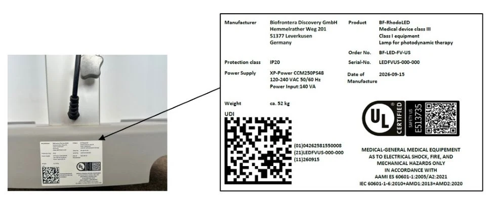
Figure 18: Product labels — the serial number, manufacturing date, and UDI DataMatrix are variable.
Labels with safety instructions, special disposal instructions and further instructions are represented in the following figures.
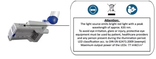
Figure 19: Instructions and notes on the lamp head
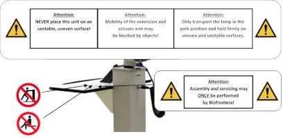
Figure 20: Instructions on the storage shelf. (The appearance of devices from batches 001 to 003 slightly differs. Appearance and location of the labels remain unaltered.)
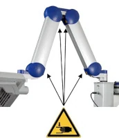
Figure 21: Instructions on the scissors arm. (The appearance of devices from batches 001 to 003 slightly differs. Appearance and location of the labels remain unaltered.)
Instructions for existing ground connector connections (see Figure 22) are located:
Next to the grounding screws, which are located within and next to the power supply cover box beneath the mobile castor, respectively
On the power supply cover box (see Figure 23)

Figure 22: Instructions for ground connector connection
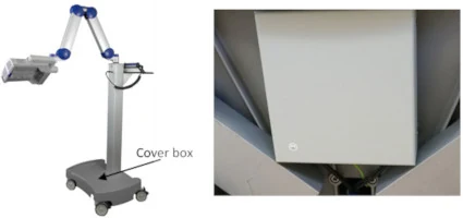
Figure 23: BF-RhodoLED®. (The appearance of devices from batches 001 to 003 slightly differs. Appearance and location of the labels remain unaltered.)
Instructions on the existing potential compensator conductor is located on the carrier bar beneath the potential compensator conductor (see Figure 24).
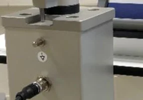
Figure 24: Potential compensator conductor. (The appearance of devices from batches 001 to 003 slightly differs. Appearance and location of the labels remain unaltered.)
All depicted symbols are summarized in a table in section 13.2 "Explanation of symbols".
13.2 Description of Symbols
Symbol
Description
Eye protection is required.
IP20
IP (Ingress Protection):
Protection class of the housing against contact, foreign bodies and water
2 = against ingress of solid foreign bodies ≥ 12.5 mm Ø and larger
0 = Not protected against water

Technical and electric devices must not be disposed of with household waste. Please pay attention to the applicable disposal instructions found in the user manual.

Symbol for existing ground connector connections

Follow the instructions for use!

General warning signs:
Assembly and servicing may ONLY be performed by Biofrontera!
Only transport lamp in the park position!
The mobility of the extension and scissors arm may be obstructed by objects!
Caution: heavy, do NOT lift alone.
NEVER place this unit on an unstable, uneven surface!

Warning sign - risk of trapping fingers!

Symbol for existing potential compensation conductor
Function/Application:
The purpose of a potential compensation conductor is to connect all conducting, metallic parts of a system to each other by the protective earthing in order to achieve the same electrical potential for the connected parts. Protection against contact voltage is thus guaranteed. Releasing the potential compensation conductor is forbidden. It should be firmly fitted to the support splint.
Please observe the requirements for ME-systems set out in EN 60601-1 when using the potential compensation cable (chapter 16).

Please do not stand on or push. There is a risk that the device may fall over due to the force applied.

Please do not sit on the equipment. There is a risk that the device may fall over due to the force applied.
13.3 Labeling on the Packaging
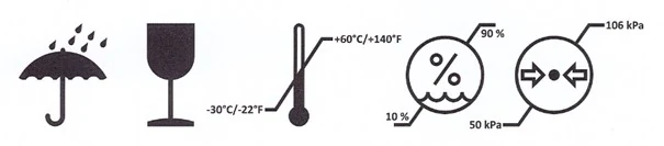
Attention: Protect from moisture and keep dry!
Attention: Do not throw the package, damage possible!
Attention: Please transport and store at -30°C/ -22°F to +60°C/ 140°F, a relative humidity of 10 % to 90 % and at an atmospheric pressure of 500 hPa (50 kPa) - 1060 hPa (106 kPa).
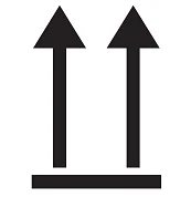
This side up!
Caution, one end of the package is heavy

Contains a lithium metal battery (optionally, not required starting from batch 007)
14 Electromagnetic compatibility (EMC)
BF-RhodoLED® meets the EMC requirements of the international standard EN60601-1-2:2015 Chapter 7 and 8. Other electrical devices can have an impact on the device. Using accessories that have not been approved can have a negative impact on the device and change the electromagnetic compatibility.
BF-RhodoLED® should not be used directly alongside or between other electrical devices.
Guidelines and manufacturer's declaration - electromagnetic emissions
BF-RhodoLED® is intended for operation in the electromagnetic environment detailed below.
The customer or operator of the device should ensure that it is operated in this environment.
Emission readings
Conformity
Electromagnetic environment - guidelines
HF emissions CISPR 11
Group 1
BF-RhodoLED® only uses HF energy for its internal functionality.
For this reason, its HF emission is very low and it is not likely that neighbouring electronic devices would be disturbed.
HF emissions in accordance with CISPR 11
Harmonics in accordance with IEC 61000-3-2
Voltage fluctuations/flickers in accordance with IEC 61000 3-3
Class B
Class A
In compliance
BF-RhodoLED® is intended for operation in non-residential facilities and similar environments that are connected directly to a public low-voltage supply network that also supplies residential buildings.
Guidelines and manufacturer's declaration - electromagnetic immunity
BF-RhodoLED® is intended for operation in the electromagnetic environment detailed below.
The customer or operator of the device should ensure that it is operated in this environment.
Immunity tests
IEC 60601 test levels
Compliance level
Electromagnetic environment - guidelines
Static discharge in accordance with IEC 61000-4-2
±8 kV contact discharge ±2 kV, ±4 kV, ±8 kV and ±15 kV air discharge
±8 kV contact discharge ±2 kV, ±4 kV, ±8 kV and ±15 kV air discharge
Floors should be made of wood or concrete or finished with ceramic tiles. If the floor is finished with synthetic material, the relative air humidity must be at least 30 %.
Fast, transient electrical disturbances/bursts in accordance with IEC 61000-4-4
±2 kV for mains lines ±1 kV for input and output lines
±2 kV for mains lines
The quality of the supply voltage should correspond to that of a typical commercial or hospital environment.
Surges in accordance with IEC 61000-4-5
±1 kV voltage outer conductor - outer conductor ±2 kV outer conductor - earth
±1 kV voltage outer conductor - outer conductor ±2 kV outer conductor - earth
The quality of the supply voltage should correspond to that of a typical commercial or hospital environment.
Voltage drops, brief interruptions and fluctuations in the supply voltage in accordance with IEC 61000-4-11
0 % UT for 0.5 cycles at phase angles of 0°, 45°, 90°, 135°, 180°, 225°, 270° and 315° (applicable only to me equipment connected to single-phase a.c. mains)
0 % UT for 1 cycle
70 % UT for 25/30 cycles
0 % UT for 250/300 cycles
0 % UT for 0.5 cycles at phase angles of 0°, 45°, 90°, 135°, 180°, 225°, 270° and 315° (applicable only to me equipment connected to single-phase a.c. mains)
0 % UT for 1 cycle
70 % UT for 25/30 cycles
0 % UT for 250/300 cycles
The quality of the supply voltage should correspond to that of a typical commercial or hospital environment.
If the operator of the device needs functionality to be maintained despite interruptions in the energy supply, it is advisable to run the device on an uninterruptable power supply or a battery.
Power frequency (50/60 Hz) magnetic field in accordance with IEC 61000-4-8
3 A/m
3 A/m
Mains frequency magnetic fields should correspond to the values typically found in the commercial and hospital
environment.
Comment: UT is the mains AC voltage prior to application of the test level
Guidelines and manufacturer's declaration - electromagnetic immunity
BF-RhodoLED® is intended for operation in the electromagnetic environment detailed below. The customer or operator of the device should ensure that it is operated in this environment.
Immunity tests
IEC 60601 test levels
Compliance level
Electromagnetic environment - guidelines
Conducted HF disturbances in accordance with IEC 61000-4-6
Radiated HF disturbances in accordance with IEC 61000-4-3
3 V
150 kHz to 80 MHz
6 V
ISM bands 0.15 - 80 MHz
80 % AM with 1 kHz
3 V/m 80 MHz to 2.7 GHz
80 % AM with 1 kHz
3 V
6 V
3 V/m
Portable and mobile communication devices should not be used in closer proximity to the unit or its cables than the recommended safety distance of 300 mm.
Interference may occur in the vicinity of equipment marked with the following symbol.

Comment 1: These guidelines may not be applicable in all cases. The propagation of electromagnetic values is influenced by absorptions and reflections of buildings, objects, and people.
Recommended safety distances between portable and mobile HF telecommunication devices and the BF-RhodoLED®
The BF-RhodoLED® is intended for use in the electromagnetic environment in which the HF disturbances are controlled.
The customer or operator of the device can help to avoid electromagnetic interference by maintaining the minimum safe distance between portable and mobile high-frequency telecommunication devices (transmitters) and the device. Portable RF communications equipment (radios, including their accessories such as antenna cables and external antennas) should not be used at a distance less than 30 cm (or 12 inches) from the manufacturer's specified parts and leads of the BF-RhodoLED®. Failure to do so may result in a reduction in the performance of the device.
BF-RhodoLED® should not be used directly alongside or between other electrical equipment.
Guidelines and manufacturer's declaration - proximity fields from RF wireless communication equipment
BF-RhodoLED® is intended for operation in the electromagnetic environment detailed below.
The customer or operator of the device should ensure that it is operated in this environment.
Service
Frequency range/ discrete frequencies MHz
Compliance level
[V/m]
TETRA 400
390
27
GMRS 460, FRS 460
430
28
LTE Band 13, 17
734
746
788
9
GSM 800/900, TETRA 800,
iDEN 820, CDMA,
LTE Band 5
821
862
948
28
GSM 1800, CDMA 1900,
GSM 1900,DECT,
LTE Band 1,3,4, 25
1730
1825
1970
28
Bluetooth, WLAN, 802.11 b/g/n, RFID 2450, LTE Band 7
2452
28
WLAN 802.11
a/n
5240
5500
5700
9
Version 2.0
INSTRUCTION FOR USE

User Manual
Manufacturer: Biofrontera Discovery GmbH
Distributor: Biofrontera Inc.
Foreword
Thank you for choosing the RhodoLED® XL LED lamp for your photodynamic therapy. RhodoLED® XL has been developed in accordance with applicable technical standards to provide high energy efficiency as well as constant light emission at the desired wavelength.
Your lamp must be installed and maintained by a qualified Biofrontera technician and used only in accordance with the instructions in this manual. You may request the latest printed version covering this model from Biofrontera at any time.
Our drug Ameluz® and medical device RhodoLED® XL have been approved in combination for photodynamic therapy; the only approved use of our lamp is in combination with Ameluz® gel. This user manual provides important RhodoLED® XL product details, precautions and warnings, and operating instructions. For Ameluz®, please use its US prescribing information (USPI). The Ameluz® prescribing information includes information on how to use the gel along with contraindications, warnings and precautions, and dosage and administration.
The product labels/ markings shown in this manual are examples. They may differ slightly from those on the lamp.
Thorough reading and use of both this user manual and the Ameluz® USPI is required prior to treatment.
Our combination Ameluz®/RhodoLED® XL for photodynamic therapy is only to be used by physicians or healthcare professionals.
For further questions about Ameluz®, RhodoLED® XL, or the combination therapy, please contact your sales representative or Biofrontera (Ameluz-US@biofrontera.com). See contact information below or visit us at http://www.biofrontera.us.com/
Sales representative:
Name:
Tel.:
E-mail:
Biofrontera Inc.
660 Main Street
1st Floor
Woburn, MA 01801
USA
Phone: (844) 426-3589
Warranty and Disclaimers
Please see the terms and conditions of your contract for this information.
Manufacturer
Biofrontera Discovery GmbH, Hemmelrather Weg 201, 51377 Leverkusen, Germany
"AMELUZ and RHODOLED are registered trademarks of Biofrontera Inc. ©2026 Biofrontera Inc. All rights reserved.”
1 Intended Use
RhodoLED® XL is a red light-emitting LED lamp, which is used exclusively in combination with Ameluz® gel for the treatment of:
lesion-directed and field-directed treatment of actinic keratoses (AKs) of mild-to-moderate severity on the face and scalp.
superficial basal cell carcinoma (sBCC).
2 RhodoLED® XL - General Description
RhodoLED® XL is comprised of three main components, the lamp head, an easily adjustable spring arm, and the mobile base with castors for smooth transport. In addition, the lamp has a convenient touchscreen monitor and aids for positioning the lamp head. The device is connected to the mains via a fixed mains supply cable.
3 Warnings and Precautions

The RhodoLED® XL has been developed for use in photodynamic therapy in combination with Ameluz® gel (excitation wavelength 635 nm). Any other use or combination of use is prohibited.
During PDT side-effects such as application site erythema, pain, irritation, edema, pruritus, exfoliation, scab, induration and vesicles may occur. For further information please see Ameluz® USPI section 6.

The user manual must be read carefully prior to using the RhodoLED® XL.
The RhodoLED® XL may only be used by healthcare professionals who have received adequate training in its use.

Bright light, do not stare into the light source

Protective eye wear must be used by patient, healthcare providers and any persons present during the illumination period.
Do not stare in the LED beam. LEDs are classified in the exempt group according to IEC 62471:2006.

Distance sensor of RhodoLED® XL is a class 1 laser product in compliance with IEC 60825-1:2014. A class 1 laser product is safe under all conditions of normal use.

Risk of trapping fingers!
Depending on positioning, fingers can be trapped
between LED panels,
between LED panels and the holding bracket,
between the movable part and the fixed part of the lamp head holding bracket.
Neither the RhodoLED® XL nor the power supply unit should be exposed to excessive mechanical stress or serviced by unauthorized personnel. Assembly and servicing may only be carried out by Biofrontera qualified professionals.
In order to avoid the risk of electrical shock, the device may only be connected to a power supply with a grounded connection.
Neither the RhodoLED® XL nor its control unit may come into contact with water as this may lead to severe damage or electrical shock (exception: cleaning with a damp cloth).

The RhodoLED® XL should be operated and housed indoors in areas with temperatures between 59 °F and 86 °F (15 °C and 30 °C), and relative humidity of 10 % to 90 %.
Medical electronic devices require special precautionary measures with regard to the electro-magnetic compatibility (EMC); to avoid electro-magnetic disturbances, please do not place the device close to other electrical devices.
There is a risk of tripping over the power cord or the lamp base. When transporting or when device is not in use, unplug and keep the power cord rolled up.
Ensure that the control unit is always returned to parking position to avoid damage during transport.
The control unit should not be exposed to strong external pressure or sharp objects.
A person trained in operation of the RhodoLED® XL must always be present during treatment.
Before treating affected skin area with the topical medication check the proper functioning of the RhodoLED® XL. Do not use a damaged device for treatment.
RhodoLED® XL is intended for operation in non-residential facilities and similar environments that are connected directly to a public low-voltage supply network that also supplies residential buildings. RhodoLED® XL shall be operated in environments of professional health care facilities except in the vicinity of RF surgical equipment and outside the RF-shielded room of a magnetic resonance imaging system
The RhodoLED® XL LED panels should only be used in curved shape and not in fully unfolded form. This is necessary to ensure the application of 37 J/cm² during the illumination.
Do not place the device in such a way that it is difficult to disconnect the device's power plug from the mains during operation.
The device must be protected against unauthorized use.
Maintenance and initial set up of the RhodoLED® XL must be carried out by authorized personnel. In the event of servicing or set up being carried out by any other party, Biofrontera assumes no responsibility or liability regarding the safety or use of the device.
4 RhodoLED® XL Technical Description
4.1 Light emitting diodes (LED)
RhodoLED® XL is a red-light emitting LED lamp, comprised of three main components, the lamp head, an easily adjustable spring arm, and the mobile base with castors for smooth transport. In addition, the lamp has a convenient touchscreen monitor and aids for positioning the lamp head. RhodoLED® XL has 45 LEDs per panel with a total of 5 panels (225 LEDs), which emit a uniform, visible red light. The typical peak wavelength is approximately 635 nm with a half-band width of 16 nm.
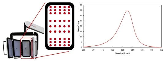
Figure 1: LED panels with LED distribution and emission spectrum of RhodoLED® XL LEDs.
The RhodoLED® XL LEDs are calibrated such that the skin being treated receives a light dose of approximately 37 J/cm2 under the following conditions:
- Illumination time of 10 minutes
- Treatment distance of 4.9 ± 0.6 inches (12.5 cm ± 1.5 cm)
The illumination area of the LED lamp is 9.06 x 11.42 inches (23 cm x 29 cm) for all panels in a curved shape.
The LEDs are distributed on each panel in a specific way (see Figure 1), such that they are more densely packed towards the upper and lower edges than in the center region of each panel. This distribution optimizes the homogeneity of illumination over the treated skin.
4.2 RhodoLED® XL Components
The RhodoLED® XL consists of the following main components (Figure 2):
Lamp head with telescope suspension
Spring arm
Control unit
Mobile base (includes support rail, castors and power supply)
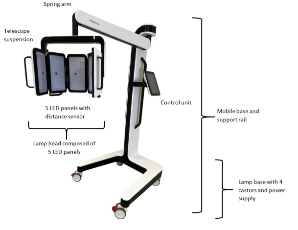
Figure 2: RhodoLED® XL main components
5 Operating environment of RhodoLED® XL
RhodoLED® XL shall be operated in environments of professional health care facilities. For a detailed description of electromagnetic compatibility see chapter 15. RhodoLED® XL is intended for operation in non-residential facilities and similar environments that are connected directly to a public low-voltage supply network that also supplies residential buildings.
6 Eye Protection
Protective eye wear must be used by patient, healthcare providers, and any persons present during the illumination period. Do not stare into the LED beam. RhodoLED® XL LEDs are classified in the exempt group product according to IEC 62471:2006. The operator and other persons present must wear protective glasses with a visible light transmission (VLT) of approximately 10 %. The patient must wear eye protection such as disposable eye protection pads or eye caps with an optical density for visible light of 6 or higher. Both options are effective and comfortable for use during treatment.
Note: Eyewear is not part of the medical device. Please carefully read any accompanying usage information before using any eye protection.
Protective eye wear must be used by patient, healthcare providers and any persons present during the illumination period.
Do not stare in the LED beam. LEDs are classified in the exempt group according to IEC 62471:2006.
7 RhodoLED® XL PDT Summarized Step-by-Step Instruction
These instructions should be used in conjunction with detailed operating instructions below (chapter 8). The section titles and numbers listed next to the instruction refer to the detailed instructions that correspond with each step.
Note: Every user of the RhodoLED® XL must be trained in operating the device. The initial training is provided by Biofrontera during set-up of the RhodoLED® XL. Recurrent training is not mandatory but can be provided by Biofrontera employees or other authorized parties. Before treating a patient with Ameluz®, please ensure that RhodoLED® XL is in good working order.
STEP 1)
Plug in the lamp.
STEP 2)
Turn on the lamp and wait for the home screen to appear (see chapter 8.4.3).
STEP 3)
Check the proper functioning of the RhodoLED® XL.
STEP 4)
Treat the affected skin area: Application, incubation, and removal of the topical medication according to the USPI of Ameluz®.
STEP 5)
Position the patient comfortably and equip the patient with protective eyewear (see chapter 6).
STEP 6)
Select active panels (see chapter 8.4.5).
STEP 7)
Position the lamp and adjust the lamp head over the skin area to be treated (distance 4.9 inches /12.5 cm) (see chapter 8.4.6).
STEP 8)
Put on protective eyewear and make sure anyone remaining in the treatment room also wears protective eyewear (see chapter 6).
STEP 9)
Start treatment by pressing Start, the illumination period begins (see chapter 8.4.9).
Remind the patient to remain still throughout the illumination period.
If audible indicators during treatment are activated, explain the sounds to the patient.
If the patient needs a break, press Pause on the screen.
To resume treatment, press Resume (see chapter 8.4.10).
To abort the illumination, press Cancel (see chapter 8.4.10).
Always stay with the patient during the illumination period.
STEP 10)
At the end of the illumination period, remove patient's protective eyewear and follow further instructions in the Ameluz® USPI.
8 Detailed Operating Instructions
Note: Every user of the RhodoLED® XL must be trained in operating the device. The initial training is provided by Biofrontera during set-up of the RhodoLED® XL. Recurrent training is not mandatory but can be provided by Biofrontera employees. The device must be protected against unauthorized use.
Protective eye wear must be used by patient, healthcare providers and any persons present during the illumination period.
Do not stare in the LED beam. LEDs are classified in the exempt group according to IEC 62471:2006.
8.1 Transport of RhodoLED® XL and Spring Arm Lock Function
During transportation the RhodoLED® XL must be in the transport position (see Figure 3). For the transport position the spring arm is moved down as far as possible and the locking bolt at the joint between head and spring is moved to the right (Figure 3). In this position, the spring arm is locked and cannot be moved upwards. To release the spring arm lock, push the locking bolt to the left (Figure 3). The locking function is located at the bottom of the spring arm, close to the lamp head connection.
For transport, please ensure that the control unit of RhodoLED® XL is placed on the left side (see Figure 3).
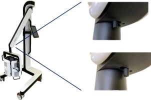
Figure 3: Transport position of RhodoLED® XL and locking function of spring arm. Locking function is located at the bottom of the spring arm, close to the lamp head connection.
8.2 Movement Areas
The swivel range of the spring arm to the left and right of the main axis is +/- 5°. The vertical range of the spring arm is 68°. The spring arm with internal gas spring allows seamless adjustment to any height. The lamp head can be rotated by 360° (Figure 4). In addition, the panels can be tilted up to 90° at the holding bracket (Figure 4).
Note: If the spring arm is at the top, it may collide with the LED panels when they are rotated 360°.
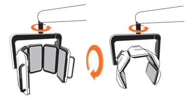
Figure 4: Rotation and tilting of the lamp head.
The orientation of the panels can be changed from a curved shape to an unfolded form by pulling the holding bracket apart (Figure 5).
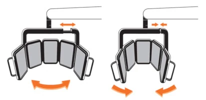
Figure 5: Movement range of the lamp head.
Note: The RhodoLED® XL LED panels should only be used in curved shape and not in a fully unfolded form. This is necessary to ensure the application of 37 J/cm² during the illumination.
The control unit can be turned from the left to the right side of the device (see Figure 6). The control unit must be brought completely into the selected position until it snaps into place.
Note: If the control unit is not snapped into position, there may be a collision between the spring arm and the control unit.
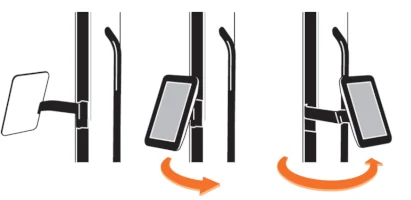
Figure 6: Control unit positions
8.3 Turning RhodoLED® XL On and Off
Note: Before turning on the lamp, the power cord must be plugged into a power outlet. RhodoLED® XL is intended for operation in non-residential facilities and similar environments that are connected directly to a public low-voltage supply network that also supplies residential buildings.
Note: Do not place the device in such a way that it is difficult to disconnect the device's power plug from the power supply during operation.
The RhodoLED® XL is equipped with a cable winding system. To unwind the cable, pull the plug out of the opening of the lamp base. When the cable is being unwound, a clicking sound is heard. The power button is located on the right side of the control unit. With the lamp plugged in, press the power button to start the device.
To power down the device, press the power button and the device shuts down. RhodoLED® XL can also be switched off via the software. To switch the device off, press the software power button in the upper right corner. To rewind the cable, remove the plug from the wall socket and slightly pull on the cable once. Hold the cable loosely in your hand to allow rewinding. The cable winder will pull the cable in automatically until it is fully rolled up. Do not completely release the cable when winding it up to avoid damage of the device.
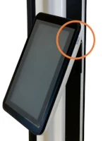
Figure 7: Control unit of RhodoLED® XL with power button
8.4 RhodoLED® XL Controls
8.4.1 Control Unit
The touchscreen of the control unit can be used while wearing commercially available examination gloves.
8.4.2 Splash Screen
The Biofrontera corporate logo and software version are displayed during the LED lamp operating system start-up (Figure 8). The operating system takes approximately 10 seconds to load.

Figure 8: Splash screen
8.4.3 Home Screen
The home screen appears after the operating system has loaded.
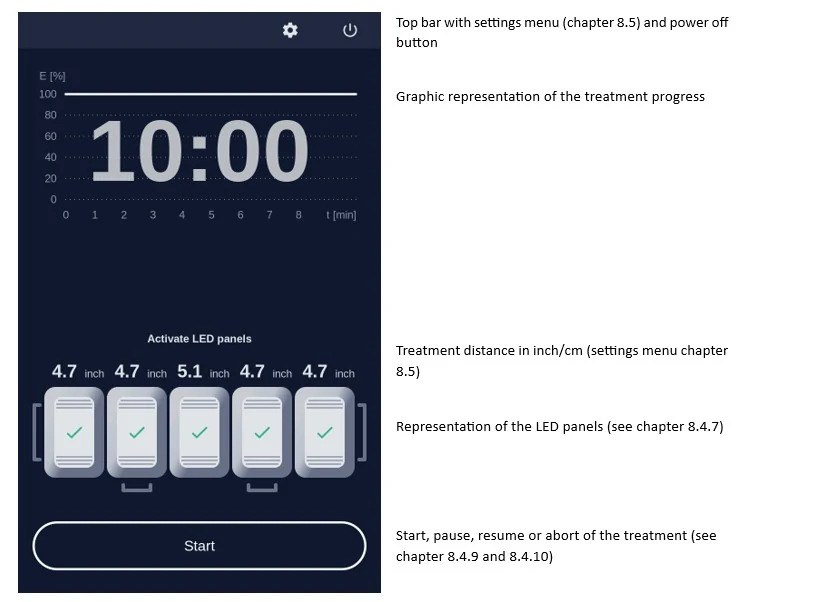
Figure 9: Home screen
8.4.4 The Treatment Profile
The RhodoLED® XL has a fixed LED light intensity which ensures the application of 37 J/cm² within the 10-minute treatment time.
8.4.5 Selecting Active LED Panels
The device has 5 LED panels which are also displayed by the software (Figure 10). The illustrated panels are visible from the back side and the corresponding panel of the device can be identified via the handles, starting from the left. All panels are activated by default and can be deactivated via the software. To deactivate LED panels, press on the illustrated panel. For easier orientation, the panel number can also be found at the backside of the respective panel (Figure 11).
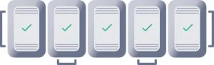
Figure 10: Software illustration of RhodoLED® XL LED panels (all panels are activated)
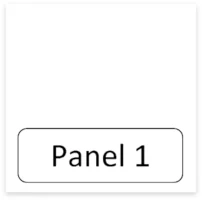
Figure 11: Panel number at the backside of the panel
Deactivated panels are displayed in grey with a power symbol in their centers (Figure 12). Activated panels are highlighted and the current distance to the treatment area is displayed.
Figure 12: Coloring of a switched off panel
8.4.6 Treatment Area
The illumination area of RhodoLED® XL is 9.06 x 11.42 inches (23 cm x 29 cm) when all panels are arranged in the standard curved shape. This usually allows a full-face illumination. However, face and head sizes are subject to strong variations between patients. As a rough guidance, the midlines of the outer two panels marks the outer boundaries of the illumination area (see Figure 13 as guidance).
Note: The RhodoLED® XL LED panels should only be used in curved shape and not in fully unfolded form. This is necessary to ensure the application of 37 J/cm² during the illumination.
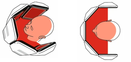
Figure 13: Treatment area of RhodoLED® XL from the side and in top view.
Note: If less than 5 panels are used for a treatment, it must be ensured that at least three adjacent panels are used. The treatment area is thereby reduced and reaches from the midline of one outer panel to the midline of the other outer panel.
If a treatment with less than 5 active LED panels is started, a message dialog appears which must be confirmed.
8.4.7 Adjusting the Treatment Distance
The correct treatment distance for the RhodoLED® XL is 4.9 ± 0.6 inches (12.5 ± 1.5 cm). Each LED panel is equipped with a distance sensor to allow individual adjustment of all panels. The distance sensor is automatically switched on if the panel is switched on. The current distance of each panel is shown on the control unit display above the panel illustration. The following table summarizes the visualization of the treatment distance.
Note: When starting the treatment, the LED panels that are too close or too far away from the treatment area will nevertheless also light up. To disable an LED panel during the treatment it must be switched off on the display (see Figure 12).
Table 1: Adjusting the treatment distance
Pictogram
Meaning

Treatment distance is correct for this LED panel (4.9 ± 0.6 inches / 12.5 ± 1.5 cm), adjustment light is/turns on

Treatment distance is too small for this LED panel. LED panel must be further away from treatment area, adjustment light is/turns off

Treatment distance is too large for this LED panel. LED panel must be closer to the treatment area, adjustment light is/turns off

This LED panel is switched off
8.4.8 Adjustment Light
If the correct treatment distance of 4.9 inches (12.5 cm) is set the LEDs of the panel light up at a low light intensity to allow an easy adjustment of the distance and the target treatment area.
The size of the treatment area is 9.06 x 11.42 inches (23 cm x 29 cm) for all panels in a curved shape.
Note: When starting the treatment, the LED panels that are too close or too far away from the treatment area will nevertheless also light up. To disable an LED panel during the treatment it must be switched off on the display (see Figure 12).
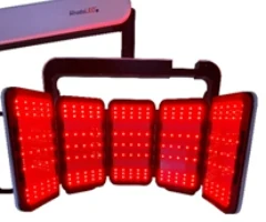
Figure 14: Low light intensity for correct adjustment of LED panels.
8.4.9 Starting an Illumination
To start a treatment, press the Start button. Before starting the treatment make sure every person present wears the correct eye protection (see chapter 6) and confirm the query for eye protection (Figure 15).
Protective eye wear must be used by patient, healthcare providers and any persons present during the illumination period.
Do not stare in the LED beam. LEDs are classified in the exempt group according to IEC 62471:2006.
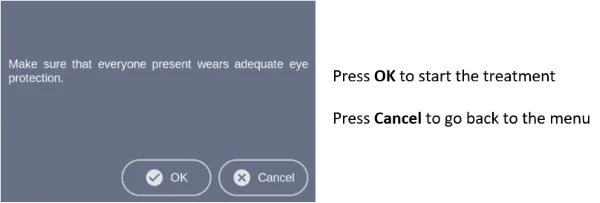
Figure 15: Note on eye protection before starting treatment.
During the illumination, the remaining treatment time is displayed in the diagram. The progress is marked green in the profile and with a green dotted vertical line (Figure 16).
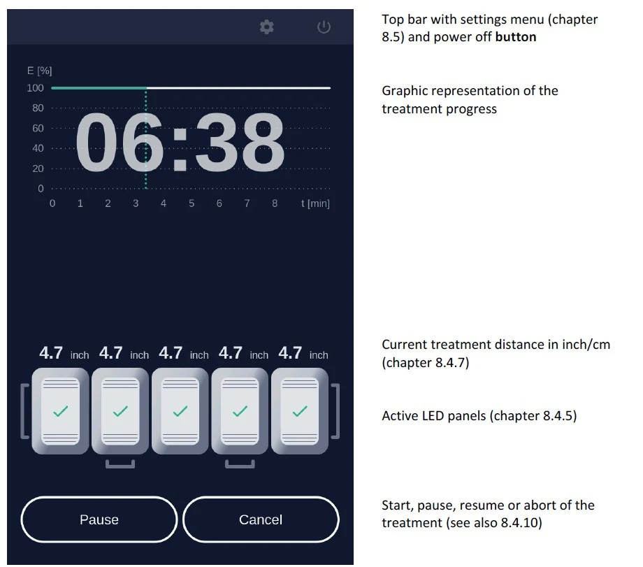
Figure 16: Treatment progress.
8.4.10 Pause, continue, or cancel a treatment
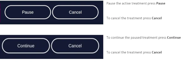
Figure 17: Pause, continue, and cancel a treatment.
To abort the current treatment, press the Cancel button. The applied light dose and the remaining treatment time is displayed in a query. Confirm the query to cancel the treatment (Figure 18).
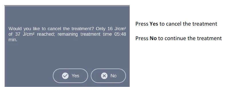
Figure 18: Cancelled treatment message shows applied light dose and remaining treatment time.
Note: If you cancel prior to the end of the total treatment time, the internal timer will reset. The remaining treatment time will not be saved.
After pressing Cancel and Yes or upon completion of the treatment the software will automatically return to the home screen.
8.4.11 Audio Signals After Treatment
After completion of the treatment a signal occurs, and the lamp will stop the illumination. Audio signals can be deactivated via the settings menu (see chapter 8.5.4).
Further audio signals occur for queries that must be confirmed and may occur in the event of an error. A description of possible errors can be found in chapter 9.
8.5 Settings Menu

To open the settings menu, select the gear symbol in the upper right corner of the screen.
The settings menu is organized in the tabs General, Service and Info.
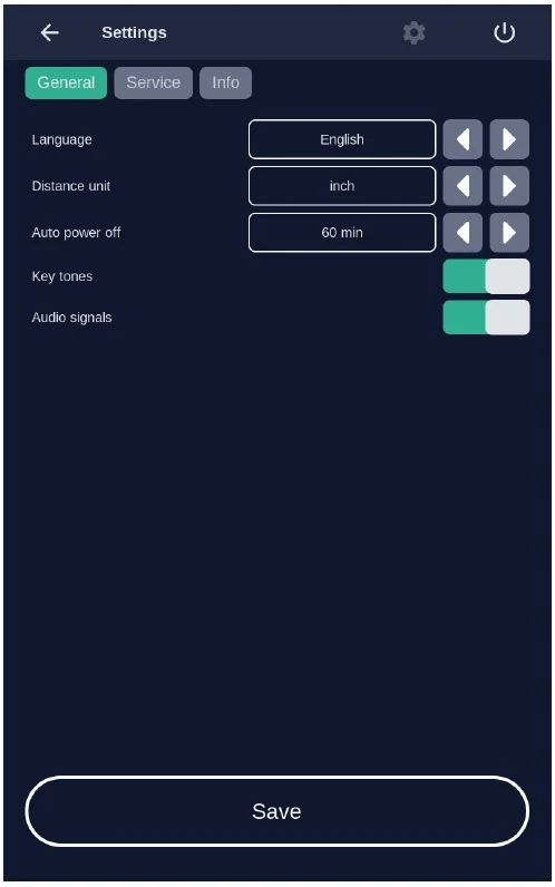
Figure 19: The settings menu is organized in the three main tabs General, Service and Info
8.5.1 Language
Language settings are part of the General settings tab. Select a language by tapping on the left and right arrows. The software provides the languages English, Spanish and German.
Confirm the selected language by pressing the Save button, to discard the settings leave the menu without pressing Save.
8.5.2 Distance Units
Unit settings are part of the General settings tab. The distance of the LED panels to the treatment area can be displayed in inches or in cm. Select a distance unit by tapping on the arrows.
Confirm the selected distance unit by pressing the Save button, to discard the settings leave the menu without pressing Save.
8.5.3 Auto power off
Auto power off settings are part of the General settings tab. The auto power off setting is used to set the time after which the lamp is automatically switched off. Values of 15, 30, 60 and 120 minutes can be selected.
Confirm your selected auto power off time by pressing Save, to discard the settings leave the menu without pressing Save.
8.5.4 Sound Settings
Sound settings are part of the General settings tab. Activate and deactivate the audio signals for typing and sounds during the treatment. To do this, activate or deactivate the corresponding sliding switch. A green slider means the sound is currently switched on.
Confirm your selection by pressing Save, to discard the settings leave the menu without pressing Save.
Note: The audio signals are very low in volume and may not be audible to the patient during operation.
Note: Warning sounds will be emitted if an error occurs during operation of the lamp. Warning sounds cannot be turned off.
8.5.5 Info-Tab
The system status provides information about the current hardware and software status of the device.
This includes information about:
- The serial numbers of the systems core components
- Automatic switch off settings
- Software version
- List of occurred errors (chapter 9)
Note: In case of a malfunction of the device, please have this information available.
8.5.6 Service Menu

Authorization is required to access the service menu. Only authorized personnel can access the service menu. See also chapter 10.
9 Error Messages
The RhodoLED® XL has an integrated monitoring function. In the event of a malfunction, an error message will appear in the message display. Possible error messages are set out in the table below. Please ensure that you always correctly record the error code when contacting Biofrontera customer service in case of an error message.
Note: even if usage of the lamp is still possible in case of an error, please contact your local sales representative or Biofrontera if an error message persists.
Error code
Possible causes
Measures
001 System error
Error in system of the device
- Confirm the system error
- Please contact your local sales representative or Biofrontera
002 Communication error
Communication between the control unit and the LED panels disturbed
- Confirm the communication error
- Treatment can be continued by confirming the message dialog
- Please contact your local sales representative or Biofrontera
- If there is a permanent error in the communication, no further treatment is possible
003 Panel error

Error in the control of one or more LED panel
Defective LED panels are marked with a red triangle
- Confirm the Panel error
- Treatment can be continued by confirming the message dialog
- Please contact your local sales representative or Biofrontera
004 Distance sensor error
Error in control of the distance sensors
- Confirm the Distance sensor error
- Treatment can be continued by confirming the message dialog
- Please contact your local sales representative or Biofrontera
005 Update process error
The software needs updating
- Please contact your local sales representative or Biofrontera
006 Temperature sensor error
Defective temperature sensor or defect in temperature sensor control
- Confirm the Temperature sensor error
- Treatment can be continued by confirming the message dialog
- Please contact your local sales representative or Biofrontera
007 Cooling system error
The ventilators or ventilator slots are blocked
The air inlets or outlets are adversely affected
- Check the ventilators and test the air inlets and outlets
- Remove any visible foreign objects which may be present
- In case of continuing impairment of the cooling system, please contact your local sales representative or Biofrontera
The treatment is paused due to an overheated LED panel. Wait until normal temperature is reached.
The temperature is too high
- Wait until the standard temperature has been reached
- Treatment can then be resumed
If your RhodoLED® XL no longer functions properly for some unknown reason, proceed as follows:
Unplug the power supply for half a minute and then plug back into the outlet (This action prompts a software reboot).
Turn the lamp back on using the control unit and verify functionality.
Should the problem persist, please contact your sales representative or Biofrontera. The lamp may not be used until the problem has been rectified.
For all other malfunctions and difficulties with operation please contact your sales representative or Biofrontera. You will find the contact details on page 2 of the manual.
Please have the system status (chapter 8.5.5) available if you contact your sales representative or Biofrontera.
10 Servicing and repairs
Servicing and repairs may only be performed by Biofrontera-authorized personnel. For RhodoLED® XL no spare parts for replacement by the user are available.
Device is not serviced while in use with patients.
If servicing or repairs are done by third parties, RhodoLED® XL warranty is void and Biofrontera cannot be held responsible for potential malfunctions of or damages to the device or the patients.
Figure 20: Servicing and maintenance may only be performed by Biofrontera
11 Maintenance and Cleaning
The device may under no circumstances be cleaned with aggressive cleaning agents or solvents (e.g. acetone or highly concentrated ethanol), as these promote wear and tear of the surface (paint coating) and labeling. Please use only a damp cloth when wiping over the labels.
Please avoid allowing any penetration of liquids into the lamp, as RhodoLED® XL is not waterproof and the electronics inside may be damaged. Do not maintain or clean the device while in use with patients.
Always unplug the lamp prior to cleaning and please observe the following cleaning practices:
Daily:
Wipe the plexiglass screen located on the bottom of the lamp head with a damp soft cloth (e.g., a microfiber cloth).
Weekly:
Wipe the entire lamp. Do not use a very wet or dripping cleaning cloth. The unit is not waterproof and damage could occur. Weekly cleaning can be carried out using a damp cloth, Multi-Purpose Cleaners (Clorox Healthcare VersaSure Wipes) or pre-soaked disinfection wipes based on quaternary ammonium compounds (e.g. Cavi wipes XL or Clorox disinfection wipes).
Please observe the following checks:
Monthly:
Check lamp for obvious visible damage such as damaged cables, worn off labeling, cracks on the lamp housing, etc.
Do not use a damaged device for treatment and please inform your supplier.
12 Disposal Instructions
Follow all local and governmental disposal laws and regulations when disposing of the RhodoLED® XL.
13 Technical Data
13.1 Electrical Connectors
Power supply unit:
Primary wide-range input 100-120 VAC
Secondary safety extra-low voltage output 48 VDC
Secondary standby voltage output 5 VDC
LED controller board:
Supply voltage input 48 VDC
2x CAN interface (2 pin)
LED board FFC (12 pin)
Distance sensor FFC (4 pin)
2 x connector ventilator (3 pin)
LED board:
LED controller board FFC 12 pin (3 x LED circuits, temperature)
Distance sensor FFC (4 pin)
Human Machine Interface (HMI) for operation:
Supply voltage input 48 VDC (2 pin)
Secondary standby voltage input 5 VDC (4 pin)
CAN interface (3 pin)
USB interface (5 pin, covered)
Speaker (2 pin)
Touch controller (4 pin)
Display data LVDS (40 pin)
On/off switch (2 pin)
HMI module to pillar external connector (10 pin)
Grounding (1 pin)
13.2 Specification
Type
RhodoLED® XL
Medical device class III; Device of protection class 1
Certification
UL certified E513735
Manual is valid for Software Version No.
g2.15.00.3911
Service interval
Biofrontera recommends performing service every 2 years
Number of LEDs
225
Typical peak wavelength
635 nm ± 5 nm
Light dose
Approx. 37 J/ cm2 at 4.9 inches (12.5 cm) distance, 10 min
Typical irradiance
approx. 60 mW/cm² ± 20 % at 4.9 inches (12.5 cm) distance
Max irradiance
approx. 72 mW/cm² at 4.9 inches (12.5 cm) distance
Illuminated area
An area of 9.06 x 11.42 inches (23 cm x 29 cm) is illuminated using all panels in curved shape.
Max. deviation of the intensity over the treatment area
Approx. 20 %
Treatment distance
4.9 ± 0.6 inches (12.5 cm ± 1.5 cm)
Measuring accuracy ± 0.3 cm (0.1 inch)
Transport conditions
Temperature: -4°F to +140°F (-20°C to +60°C)
Atmospheric pressure: 500 hPa - 1060 hPa
Relative humidity: 10% - 90%, non-condensing
Storage conditions
Temperature: +59°F to +95°F (+ 15°C to +35°C)
Atmospheric pressure: 500 hPa - 1060 hPa
Relative humidity: 10% - 90%, non-condensing
Maximum storage time 180 days
Operating conditions
Temperature: +59°F to +86°F (+15°C to + 30°C)
Atmospheric pressure: 500 hPa - 1060 hPa
Operational altitude: ≤ 4800 m above NN
Relative humidity: 10% - 90%, non-condensing.
RhodoLED® XL must be operated in environments of professional healthcare facilities.
Operating voltage
100-120 VAC, 60 Hz
Output voltage
48 VDC
Power consumption
In normal operation: approx. 750 VA
In standby mode: approx. 85 VA
Over-voltage category
II
Degree of contamination
2
Material group (CTI)
IIIb
Protection class
IP20
Size of the lamp
Height 5.76 ft (175.5 cm)
Width: 2.51 ft (76.4 cm)
Depth: 3.19 ft (97.1 cm)
Total lamp weight
165 lb. (75 kg)
For further information please directly contact Biofrontera.
14 Labeling and Symbols
14.1 Label on the Lamp Base
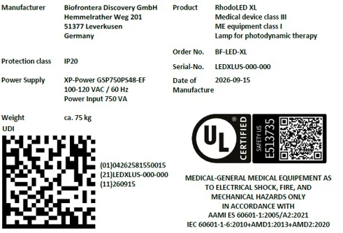
Figure 21: Product label (serial number and date of manufacturing vary) with UDI code of RhodoLED® XL on lamp base, individual code depends on the serial number and date of manufacturing of the device.
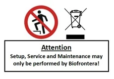
Figure 22: No stepping on the device, no disposal in household waste, information on setup and service.

Figure 23: Instruction for ground connector connection (not visible from the outside)
14.2 Label on LED Panels
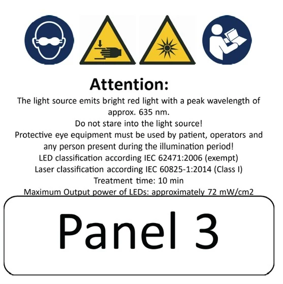
Figure 24: Instruction and notes on the LED panels
Figure 25: LED Panel numbering from Panel 1 to Panel 5
14.3 Description of Symbols
Symbol
Description
Eye protection is required.
Distance sensor of RhodoLED® XL is a class 1 laser product. A class 1 laser product is safe under all conditions of normal use.
IP20
IP (Ingress Protection):
Protection class of the housing against contact, foreign bodies and water
2 = against ingress of solid foreign bodies ≥ 12.5 mm Ø and larger
0 = Not protected against water

Technical and electric devices must not be disposed of with household waste. Please pay attention to the applicable disposal instructions found in the user manual.

Symbol for existing ground connector connections
Follow the instructions for use!
General warning signs:
Assembly and servicing may ONLY be performed by Biofrontera
Only transport lamp in the park position
Caution: heavy, do NOT lift alone.
Warning sign - risk of trapping fingers!
Bright light, do not stare into the light source

Do not step on the device.
15 Electromagnetic compatibility
RhodoLED® XL complies with the EMC requirements of IEC 60601-1-2:2014 + A1:2020. Other electrical devices can influence the device.
The use of accessories, transducers and cables other than those specified or provided by the manufacturer may result in increased electromagnetic emissions or reduced electromagnetic immunity of the equipment and may lead to incorrect operation. Assembly, service and repairs may only be performed by Biofrontera.
Guidelines and manufacturer's declaration - electromagnetic emissions
RhodoLED® XL is intended for operation in the electromagnetic environment detailed below.
The customer or operator of the device should ensure that it is operated in this environment.
The emission characteristics of RhodoLED® XL allow its use in industrial and hospital and healthcare professional environments (CISPR 11, Class A). When used in a residential environment (for which CISPR 11 normally requires Class B), this device may not provide adequate protection of radio services. The user may need to take corrective action by moving or repositioning the device.
Emission readings
Conformity
Electromagnetic environment - guidelines
HF emissions CISPR 11
Group 1
RhodoLED® XL only uses HF energy for its internal functionality. For this reason, its HF emission is very low and it is not likely that neighboring electronic devices would be disturbed.
HF emissions in accordance with CISPR 11
Class A
RhodoLED® XL is intended for operation in non-residential facilities and similar environments that are connected directly to a public low-voltage supply network that also supplies residential buildings.
Harmonics in accordance with IEC 61000-3-2
Class A
Voltage fluctuations/flickers in accordance with IEC 61000-3-3
In compliance
Guidelines and manufacturer's declaration - electromagnetic immunity
RhodoLED® XL is intended for operation in the electromagnetic environment detailed below. The customer or operator of the device should ensure that it is operated in this environment.
Immunity tests
IEC 60601 test levels
Compliance level
Electromagnetic environment - guidelines
Static discharge in accordance with IEC 61000-4-2
±8 kV contact discharge ±2 kV, ±4 kV, ±8 kV and ±15 kV air discharge
±8 kV contact discharge ±2 kV, ±4 kV, ±8 kV and ±15 kV air discharge
Floors should be made of wood or concrete or finished with ceramic tiles. If the floor is finished with synthetic material, the relative air humidity must be at least 30%.
Fast, transient electrical disturbances/bursts in accordance with IEC 61000-4-4
±2 kV for mains lines 100 kHz repetition frequency
±2 kV for mains lines
The quality of the supply voltage should correspond to that of a typical commercial or hospital environment.
Surges in accordance with IEC 61000-4-5
±1 kV voltage outer conductor - outer conductor ±2 kV outer conductor - earth
±1 kV voltage outer conductor - outer conductor ±2 kV outer conductor - earth
The quality of the supply voltage should correspond to that of a typical commercial or hospital environment.
Voltage dips, brief interruptions and fluctuations in the supply voltage in accordance with IEC 61000-4-11
0 % UT for 0.5 cycles at phase angles of 0°, 45°, 90°, 135°, 180°, 225°, 270° and 315° (applicable only to me equipment connected to single-phase a.c. mains)
0 % UT for 1 cycle
70 % UT for 25/30 cycles
0 % UT for 250/300 cycles
0 % UT for 0.5 cycles at phase angles of 0°, 45°, 90°, 135°, 180°, 225°, 270° and 315° (applicable only to me equipment connected to single-phase a.c. mains)
0 % UT for 1 cycle
70 % UT for 25/30 cycles
0 % UT for 250/300 cycles
The quality of the supply voltage should correspond to that of a typical commercial or hospital environment.
If the operator of the device needs functionality to be maintained despite interruptions in the energy supply, it is advisable to run the device on an uninterruptable power supply or a battery.
Power frequency (50/60 Hz) magnetic field in accordance with IEC 61000-4-8
30 A/m
30 A/m
Mains frequency magnetic fields should correspond to the values typically found in the commercial and hospital environment.
Comment: UT is the mains AC voltage prior to application of the test level
Guidelines and manufacturer's declaration - electromagnetic immunity
RhodoLED® XL is intended for operation in the electromagnetic environment detailed below. The customer or operator of the device should ensure that it is operated in this environment.
Immunity tests
IEC 60601 test levels
Compliance level
Electromagnetic environment - guidelines
Conducted HF disturbances
in accordance
with IEC 61000-4-6
3 V
150 kHz to 80 MHz
6 V
ISM bands 0.15 - 80 MHz
80 % AM with 1 kHz
3 V
6 V
Portable and mobile communication devices should not be used in closer proximity of the unit or its cables than the recommended safety distance of 300 mm.
Radiated HF disturbances
in accordance
with IEC 61000-4-3
3 V/m 80 MHz to 2.7 GHz
80 % AM with 1 kHz
3 V/m
Interference may occur in the vicinity of equipment marked with the following symbol.
Comment 1: These guidelines may not be applicable in all cases. The propagation of electromagnetic values is influenced by absorptions and reflections of buildings, objects, and people.
Recommended safety distances between portable and mobile HF telecommunication devices and the RhodoLED® XL.
Portable RF communications equipment (radios, including their accessories such as antenna cables and external antennas) should not be used at a distance less than 30 cm (or 12 inches) from the manufacturer's specified parts and leads of the RhodoLED® XL. Failure to do so may result in a reduction in the performance of the device.
RhodoLED® XL should not be used directly alongside or between other electrical equipment.
Guidelines and manufacturer’s declaration – proximity fields from RF wireless communication equipment
RhodoLED® XL is intended for operation in the electromagnetic environment detailed below. The customer or operator of the device should ensure that it is operated in this environment.
Service
Frequency range/ discrete frequencies MHz
Compliance level
[V/m]
TETRA 400
385
27
GMRS 460, FRS 460
450
29
LTE Band 13, 17
710
745
780
9
GSM 800/900, TETRA 800,
iDEN 820, CDMA,
LTE Band 5
810
870
930
28
GSM 1800, CDMA 1900,
GSM 1900,DECT,
LTE Band 1,3,4, 25
1720
1845
1970
28
Bluetooth, WLAN, 802.11 b/g/n, RFID 2450, LTE Band 7
2450
28
WLAN 802.11
a/n
5240
5500
5785
9
Version 3.0 SW_G2
INSTRUCTION FOR USE

C Variant
User Manual
Manufacturer: Biofrontera Discovery GmbH
Distributor: Biofrontera Inc.
Foreword
Thank you for choosing the RhodoLED® XL-C LED lamp for your photodynamic therapy. RhodoLED® XL-C has been developed in accordance with applicable technical standards to provide high energy efficiency as well as constant light emission at the desired wavelength.
Your lamp must be installed and maintained by a qualified Biofrontera technician and used only in accordance with the instructions in this manual. You may request the latest printed version covering this model from Biofrontera at any time.
Our drug Ameluz® and medical device group RhodoLED® XL-C have been approved in combination for photodynamic therapy; the only approved use of our lamp is in combination with Ameluz® gel. RhodoLED® XL-C belongs to the RhodoLED® XL product group.
This user manual provides important RhodoLED® XL-C product details, precautions and warnings, and operating instructions. For Ameluz®, please use its US prescribing information (USPI). The Ameluz® prescribing information includes information on how to use the gel along with contraindications, warnings and precautions, and dosage and administration.
The product labels/ markings shown in this manual are examples. They may differ slightly from those on the lamp.
Thorough reading and use of both this user manual and the Ameluz® USPI is required prior to treatment.
Our combination Ameluz®/RhodoLED® XL-C for photodynamic therapy is only to be used by physicians or healthcare professionals.
For further questions about Ameluz®, RhodoLED® XL-C, or the combination therapy, please contact your sales representative or Biofrontera (Ameluz-US@biofrontera.com). See contact information below or visit us at http://www.biofrontera.us.com/
Sales representative:
Name:
Tel.:
E-mail:
Biofrontera Inc.
660 Main Street
1st Floor
Woburn, MA 01801
USA
Phone: (844) 426-3589
Warranty and Disclaimers
Please see the terms and conditions of your contract for this information.
Manufacturer
Biofrontera Discovery GmbH, Hemmelrather Weg 201, 51377 Leverkusen, Germany
"AMELUZ and RHODOLED are registered trademarks of Biofrontera Inc. ©2026 Biofrontera Inc. All rights reserved.”
1 Intended Use
RhodoLED® XL-C is a red light-emitting LED lamp, which is used exclusively in combination with Ameluz® gel for the treatment of:
lesion-directed and field-directed treatment of actinic keratoses (AKs) of mild-to-moderate severity on the face and scalp.
superficial basal cell carcinoma (sBCC).
2 RhodoLED® XL-C - General Description
RhodoLED® XL-C is comprised of three main components, the lamp head, an easily adjustable spring arm, and the mobile base with castors for smooth transport. In addition, the lamp has a convenient touchscreen monitor and aids for positioning the lamp head. The device is connected to the mains via a fixed mains supply cable.
3 Warnings and Precautions

The RhodoLED® XL-C has been developed for use in photodynamic therapy in combination with Ameluz® gel (excitation wavelength approx. 635 nm). Any other use or combination of use is prohibited.
During PDT side-effects such as application site erythema, pain, irritation, edema, pruritus, exfoliation, scab, induration and vesicles may occur. For further information please see Ameluz® USPI section 6.

The user manual must be read carefully prior to using the RhodoLED® XL-C.
The RhodoLED® XL-C may only be used by healthcare professionals who have received adequate training in its use.

Bright light, do not stare into the light source

Protective eye wear must be used by patient, healthcare providers and any persons present during the illumination period.
Do not stare in the LED beam. LEDs are classified in the exempt group according to IEC 62471:2006.

Distance sensor of RhodoLED® XL-C is a class 1 laser product in compliance with IEC 60825-1:2014. A class 1 laser product is safe under all conditions of normal use.

Risk of trapping fingers!
Depending on positioning, fingers can be trapped
between LED panels and the holding bracket,
between the movable part and the fixed part of the lamp head holding bracket.
Neither the RhodoLED® XL-C nor the power supply unit should be exposed to excessive mechanical stress or serviced by unauthorized personnel. Assembly and servicing may only be carried out by Biofrontera qualified professionals.
In order to avoid the risk of electrical shock, the device may only be connected to a power supply with a grounded connection.
Neither the RhodoLED® XL-C nor its control unit may come into contact with water as this may lead to severe damage or electrical shock (exception: cleaning with a damp cloth).

The RhodoLED® XL-C should be operated and housed indoors in areas with temperatures between 59 °F and 86 °F (15 °C and 30 °C), and relative humidity of 10 % to 90 %.
Medical electronic devices require special precautionary measures with regard to the electro-magnetic compatibility (EMC); to avoid electro-magnetic disturbances, please do not place the device close to other electrical devices.
There is a risk of tripping over the power cord or the lamp base. When transporting or when device is not in use, unplug and keep the power cord rolled up.
Ensure that the control unit is always returned to parking position to avoid damage during transport.
The control unit should not be exposed to strong external pressure or sharp objects.
A person trained in operation of the RhodoLED® XL-C must always be present during treatment.
Before treating affected skin area with the topical medication check the proper functioning of the RhodoLED® XL-C. Do not use a damaged device for treatment.
RhodoLED® XL-C is intended for operation in non-residential facilities and similar environments that are connected directly to a public low-voltage supply network that also supplies residential buildings. RhodoLED® XL-C shall be operated in environments of professional health care facilities except in the vicinity of RF surgical equipment and outside the RF-shielded room of a magnetic resonance imaging system
The RhodoLED® XL-C LED panels should only be used in curved shape and not in fully unfolded form. This is necessary to ensure the application of 37 J/cm² during the illumination.
Do not place the device in such a way that it is difficult to disconnect the device's power plug from the mains during operation.
The device must be protected against unauthorized use.
Maintenance and initial set up of the RhodoLED® XL-C must be carried out by authorized personnel. In the event of servicing or set up being carried out by any other party, Biofrontera assumes no responsibility or liability regarding the safety or use of the device.
4 RhodoLED® XL-C Technical Description
4.1 Light emitting diodes (LED)
RhodoLED® XL-C is a red-light emitting LED lamp, comprised of three main components, the lamp head, an easily adjustable spring arm, and the mobile base with castors for smooth transport. In addition, the lamp has a convenient touchscreen monitor and aids for positioning the lamp head. RhodoLED® XL-C has 45 LEDs per panel with a total of 5 panels (225 LEDs), which emit a uniform, visible red light. The typical peak wavelength is approximately 635 nm with a half-band width of 16 nm.
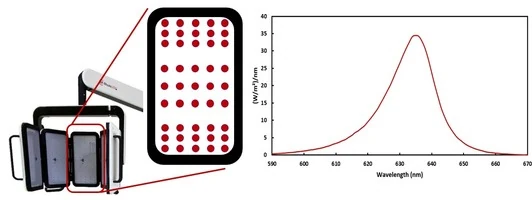
Figure 1: LED panels with LED distribution and emission spectrum of RhodoLED® XL-C LEDs.
The RhodoLED® XL-C LEDs are calibrated such that the skin being treated receives a light dose of approximately 37 J/cm2 under the following conditions:
- Illumination time of 10 minutes
- Treatment distance of 4.9 ± 0.6 inches (12.5 cm ± 1.5 cm)
The illumination area of the LED lamp is 9.06 x 11.42 inches (23 cm x 29 cm) for all panels.
The LEDs are distributed on each panel in a specific way (see Figure 1), such that they are more densely packed towards the upper and lower edges than in the center region of each panel. This distribution optimizes the homogeneity of illumination over the treated skin.
4.2 RhodoLED® XL-C Components
The RhodoLED® XL-C consists of the following main components (Figure 2):
Lamp head with telescope suspension
Spring arm
Control unit
Mobile base (includes support rail, castors and power supply)
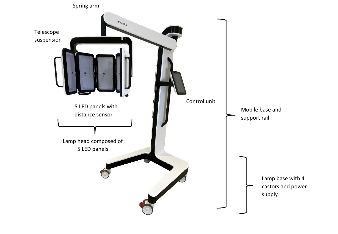
Figure 2: RhodoLED® XL-C main components
5 Operating environment of RhodoLED® XL-C
RhodoLED® XL-C shall be operated in environments of professional health care facilities. For a detailed description of electromagnetic compatibility see chapter 15. RhodoLED® XL-C is intended for operation in non-residential facilities and similar environments that are connected directly to a public low-voltage supply network that also supplies residential buildings.
6 Eye Protection
Protective eye wear must be used by patient, healthcare providers, and any persons present during the illumination period. Do not stare into the LED beam. RhodoLED® XL-C LEDs are classified in the exempt group product according to IEC 62471:2006. The operator and other persons present must wear protective glasses with a visible light transmission (VLT) of approximately 10 %. The patient must wear eye protection such as disposable eye protection pads or eye caps with an optical density for visible light of 6 or higher. Both options are effective and comfortable for use during treatment.
Note: Eyewear is not part of the medical device. Please carefully read any accompanying usage information before using any eye protection.
Protective eye wear must be used by patient, healthcare providers and any persons present during the illumination period.
Do not stare in the LED beam. LEDs are classified in the exempt group according to IEC 62471:2006.
7 RhodoLED® XL-C PDT Summarized Step-by-Step Instruction
These instructions should be used in conjunction with detailed operating instructions below (chapter 8). The section titles and numbers listed next to the instruction refer to the detailed instructions that correspond with each step.
Note: Every user of the RhodoLED® XL-C must be trained in operating the device. The initial training is provided by Biofrontera during set-up of the RhodoLED® XL-C. Recurrent training is not mandatory but can be provided by Biofrontera employees or other authorized parties. Before treating a patient with Ameluz®, please ensure that RhodoLED® XL-C is in good working order.
STEP 1)
Plug in the lamp.
STEP 2)
Turn on the lamp and wait for the home screen to appear (see chapter 8.4.3).
STEP 3)
Check the proper functioning of the RhodoLED® XL-C.
STEP 4)
Treat the affected skin area: Application, incubation, and removal of the topical medication according to the USPI of Ameluz®.
STEP 5)
Position the patient comfortably and equip the patient with protective eyewear (see chapter 0).
STEP 6)
Select active panels (see chapter 8.4.5).
STEP 7)
Position the lamp and adjust the lamp head over the skin area to be treated (distance 4.9 inches /12.5 cm) (see chapter 0).
STEP 8)
Put on protective eyewear and make sure anyone remaining in the treatment room also wears protective eyewear (see chapter 0).
STEP 9)
Start treatment by pressing Start, the illumination period begins (see chapter 8.4.9).
Remind the patient to remain still throughout the illumination period.
If audible indicators during treatment are activated, explain the sounds to the patient.
If the patient needs a break, press Pause on the screen.
To resume treatment, press Resume (see chapter 8.4.10).
To abort the illumination, press Cancel (see chapter 8.4.10).
Always stay with the patient during the illumination period.
STEP 10)
At the end of the illumination period, remove patient's protective eyewear and follow further instructions in the Ameluz® USPI.
8 Detailed Operating Instructions
Note: Every user of the RhodoLED® XL-C must be trained in operating the device. The initial training is provided by Biofrontera during set-up of the RhodoLED® XL-C. Recurrent training is not mandatory but can be provided by Biofrontera employees. The device must be protected against unauthorized use.
Protective eye wear must be used by patient, healthcare providers and any persons present during the illumination period.
Do not stare in the LED beam. LEDs are classified in the exempt group according to IEC 62471:2006.
8.1 Transport of RhodoLED® XL-C and Spring Arm Lock Function
During transportation the RhodoLED® XL-C must be in the transport position (see Figure 3). For the transport position the spring arm is moved down as far as possible and the locking bolt at the joint between head and spring is moved to the right (Figure 3). In this position, the spring arm is locked and cannot be moved upwards. To release the spring arm lock, push the locking bolt to the left (Figure 3). The locking function is located at the bottom of the spring arm, close to the lamp head connection.
For transport, please ensure that the control unit of RhodoLED® XL-C is placed on the left side (see Figure 3).
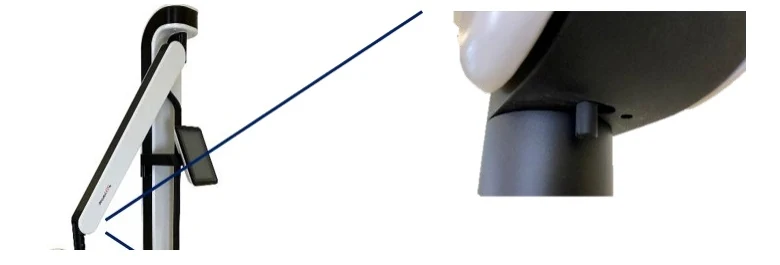
Figure 3: Transport position of RhodoLED® XL-C and locking function of spring arm. Locking function is located at the bottom of the spring arm, close to the lamp head connection.
8.2 Movement Areas
The swivel range of the spring arm to the left and right of the main axis is +/- 5°. The vertical range of the spring arm is 68°. The spring arm with internal gas spring allows seamless adjustment to any height. The lamp head can be rotated by 360° (Figure 4). In addition, the panels can be tilted up to 90° at the holding bracket (Figure 4).
Note: If the spring arm is at the top, it may collide with the LED panels when they are rotated 360°.
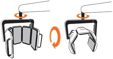
Figure 4: Rotation and tilting of the lamp head.
The control unit can be turned from the left to the right side of the device (see Figure 5). The control unit must be brought completely into the selected position until it snaps into place.
Note: If the control unit is not snapped into position, there may be a collision between the spring arm and the control unit.
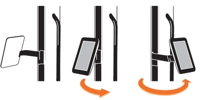
Figure 5: Control unit positions
8.3 Turning RhodoLED® XL-C On and Off
Note: Before turning on the lamp, the power cord must be plugged into a power outlet. RhodoLED® XL-C is intended for operation in non-residential facilities and similar environments that are connected directly to a public low-voltage supply network that also supplies residential buildings.
Note: Do not place the device in such a way that it is difficult to disconnect the device's power plug from the power supply during operation.
The RhodoLED® XL-C is equipped with a cable winding system. To unwind the cable, pull the plug out of the opening of the lamp base. When the cable is being unwound, a clicking sound is heard. The power button is located on the right side of the control unit. With the lamp plugged in, press the power button to start the device.
To power down the device, press the power button and the device shuts down. RhodoLED® XL-C can also be switched off via the software. To switch the device off, press the software power button in the upper right corner. To rewind the cable, remove the plug from the wall socket and slightly pull on the cable once. Hold the cable loosely in your hand to allow rewinding. The cable winder will pull the cable in automatically until it is fully rolled up. Do not completely release the cable when winding it up to avoid damage of the device.
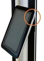
Figure 6: Control unit of RhodoLED® XL-C with power button
8.4 RhodoLED® XL-C Controls
8.4.1 Control Unit
The touchscreen of the control unit can be used while wearing commercially available examination gloves.
8.4.2 Splash Screen
The Biofrontera corporate logo and software version are displayed during the LED lamp operating system start-up (Figure 7). The operating system takes approximately 10 seconds to load.

Figure 7: Splash screen
8.4.3 Home Screen
The home screen appears after the operating system has loaded.
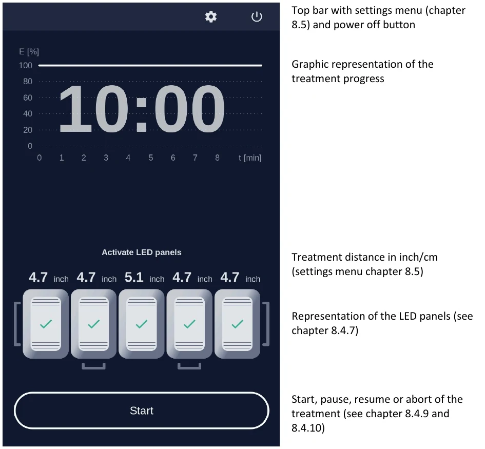
Figure 8: Home screen
8.4.4 The Treatment Profile
The RhodoLED® XL-C has a fixed LED light intensity which ensures the application of 37 J/cm² within the 10-minute treatment time.
8.4.5 Selecting Active LED Panels
The device has 5 LED panels which are also displayed by the software (Figure 9). The illustrated panels are visible from the back side and the corresponding panel of the device can be identified via the handles, starting from the left. All panels are activated by default and can be deactivated via the software. To deactivate LED panels, press on the illustrated panel. For easier orientation, the panel number can also be found at the backside of the respective panel (Figure 10).
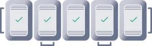
Figure 9: Software illustration of RhodoLED® XL-C LED panels (all panels are activated)
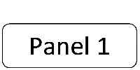
Figure 10: Panel number at the backside of the panel
Deactivated panels are displayed in grey with a power symbol in their centers (Figure 11). Activated panels are highlighted and the current distance to the treatment area is displayed.
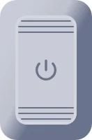
Figure 11: Coloring of a switched off panel
8.4.6 Treatment Area
The illumination area of RhodoLED® XL-C is 9.06 x 11.42 inches (23 cm x 29 cm) when all panels are arranged in the standard curved shape. This usually allows a full-face illumination. However, face and head sizes are subject to strong variations between patients. As a rough guidance, the midlines of the outer two panels marks the outer boundaries of the illumination area (see Figure 12 as guidance).
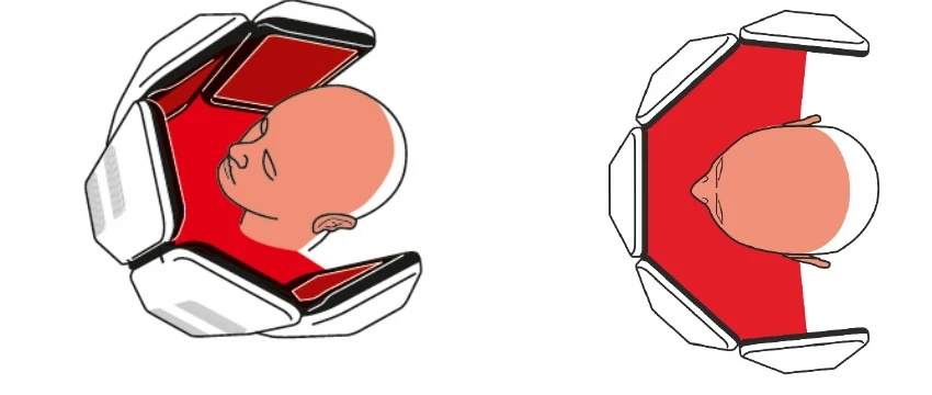
Figure 12: Treatment area of RhodoLED® XL-C from the side and in top view.
Note: If less than 5 panels are used for a treatment, it must be ensured that at least three adjacent panels are used. The treatment area is thereby reduced and reaches from the midline of one outer panel to the midline of the other outer panel.
If a treatment with less than 5 active LED panels is started, a message dialog appears which must be confirmed.
8.4.7 Adjusting the Treatment Distance
The correct treatment distance for the RhodoLED® XL-C is 4.9 ± 0.6 inches (12.5 ± 1.5 cm). Each LED panel is equipped with a distance sensor to allow individual adjustment of all panels. The distance sensor is automatically switched on if the panel is switched on. The current distance of each panel is shown on the control unit display above the panel illustration. The following table summarizes the visualization of the treatment distance.
Note: When starting the treatment, the LED panels that are too close or too far away from the treatment area will nevertheless also light up. To disable an LED panel during the treatment it must be switched off on the display (see Figure 11).
Table 1: Adjusting the treatment distance
Pictogram
Meaning

Treatment distance is correct for this LED panel (4.9 ± 0.6 inches / 12.5 ± 1.5 cm), adjustment light is/turns on
Treatment distance is too small for this LED panel. LED panel must be further away from treatment area, adjustment light is/turns off
Treatment distance is too large for this LED panel. LED panel must be closer to the treatment area, adjustment light is/turns off

This LED panel is switched off
8.4.8 Adjustment Light
If the correct treatment distance of 4.9 inches (12.5 cm) is set the LEDs of the panel light up at a low light intensity to allow an easy adjustment of the distance and the target treatment area.
The size of the treatment area is 9.06 x 11.42 inches (23 cm x 29 cm) for all panels in a curved shape.
Note: When starting the treatment, the LED panels that are too close or too far away from the treatment area will nevertheless also light up. To disable an LED panel during the treatment it must be switched off on the display (see Figure 11).
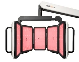
Figure 13: Low light intensity for correct adjustment of LED panels.
8.4.9 Starting an Illumination
To start a treatment, press the Start button. Before starting the treatment make sure every person present wears the correct eye protection (see chapter 0) and confirm the query for eye protection (Figure 14).
Protective eye wear must be used by patient, healthcare providers and any persons present during the illumination period.
Do not stare in the LED beam. LEDs are classified in the exempt group according to IEC 62471:2006.
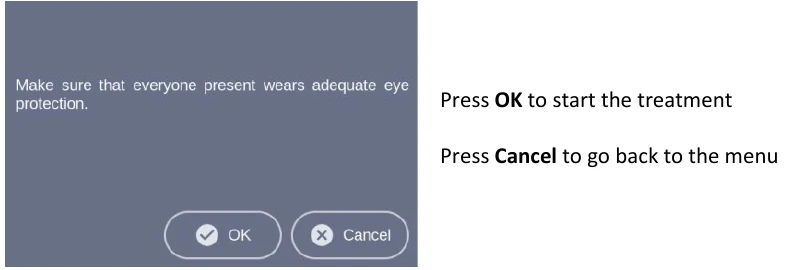
Figure 14: Note on eye protection before starting treatment.
During the illumination, the remaining treatment time is displayed in the diagram. The progress is marked green in the profile and with a green dotted vertical line (Figure 15).
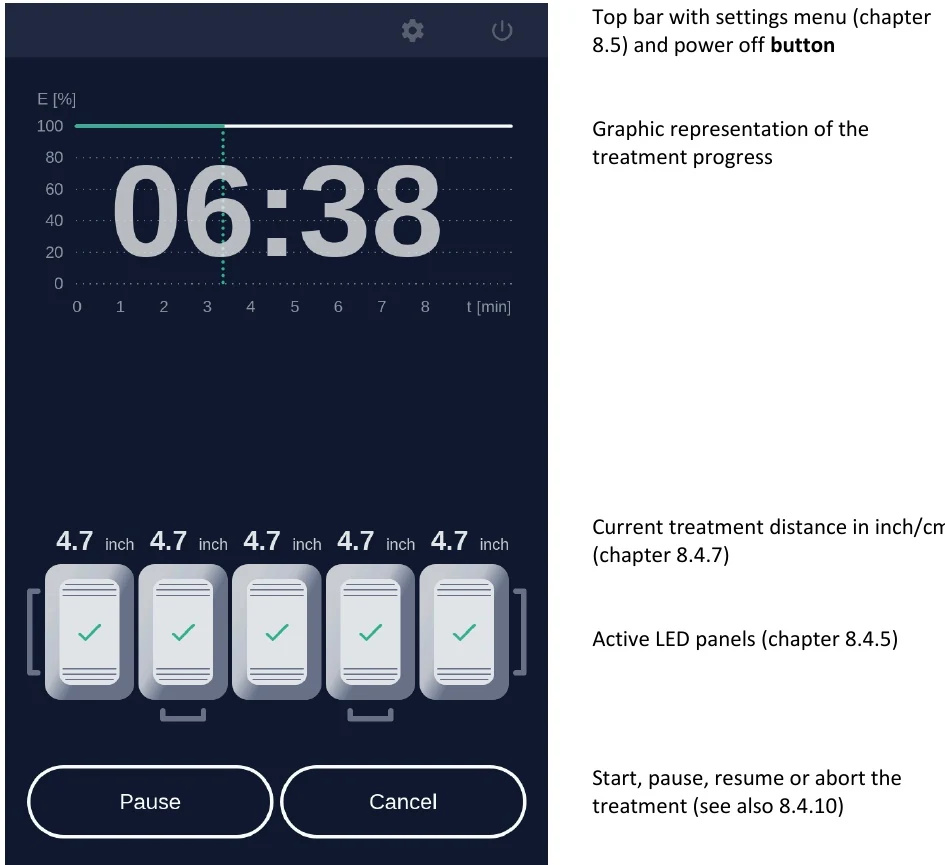
Figure 15: Treatment progress.
8.4.10 Pause, continue, or cancel a treatment
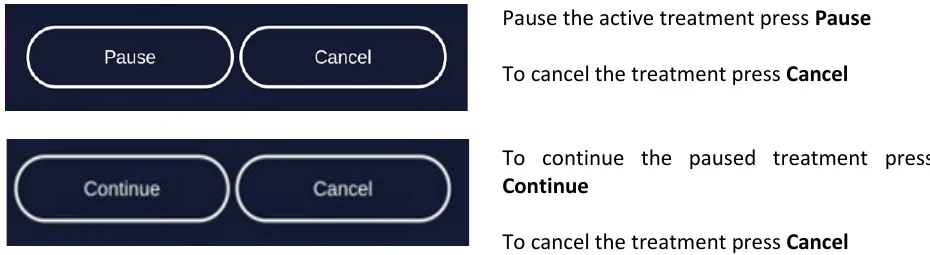
Figure 16: Pause, continue, and cancel a treatment.
To abort the current treatment, press the Cancel button. The applied light dose and the remaining treatment time is displayed in a query. Confirm the query to cancel the treatment (Figure 17).
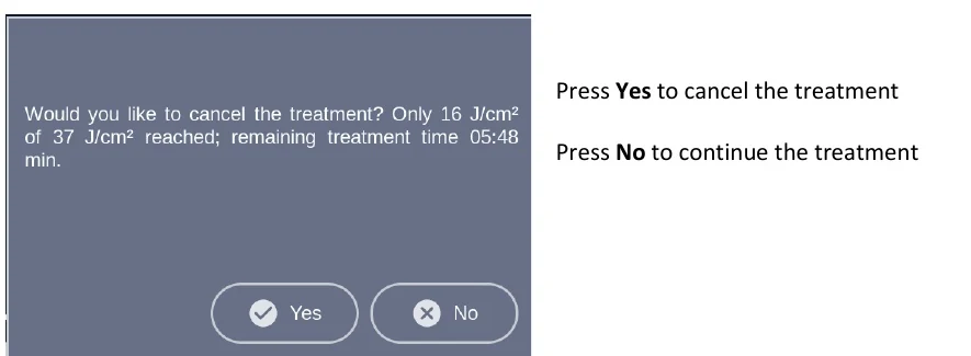
Figure 17: Cancelled treatment message shows applied light dose and remaining treatment time.
Note: If you cancel prior to the end of the total treatment time, the internal timer will reset. The remaining treatment time will not be saved.
After pressing Cancel and Yes or upon completion of the treatment the software will automatically return to the home screen.
8.4.11 Audio Signals After Treatment
After completion of the treatment a signal occurs, and the lamp will stop the illumination. Audio signals can be deactivated via the settings menu (see chapter 8.5.4).
Further audio signals occur for queries that must be confirmed and may occur in the event of an error. A description of possible errors can be found in chapter 9.
8.5 Settings Menu

To open the settings menu, select the gear symbol in the upper right corner of the screen.
The settings menu is organized in the tabs General, Service and Info.
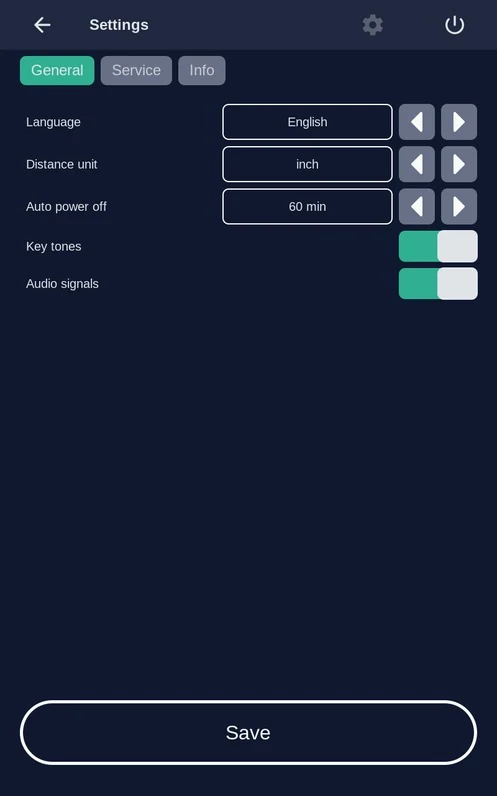
Figure 18: The settings menu is organized in the three main tabs General, Service and Info
8.5.1 Language
Language settings are part of the General settings tab. Select a language by tapping on the left and right arrows. The software provides the languages English, Spanish and German.
Confirm the selected language by pressing the Save button, to discard the settings leave the menu without pressing Save.
8.5.2 Distance Units
Unit settings are part of the General settings tab. The distance of the LED panels to the treatment area can be displayed in inches or in cm. Select a distance unit by tapping on the arrows.
Confirm the selected distance unit by pressing the Save button, to discard the settings leave the menu without pressing Save.
8.5.3 Auto power off
Auto power off settings are part of the General settings tab. The auto power off setting is used to set the time after which the lamp is automatically switched off. Values of 15, 30, 60 and 120 minutes can be selected.
Confirm your selected auto power off time by pressing Save, to discard the settings leave the menu without pressing Save.
8.5.4 Sound Settings
Sound settings are part of the General settings tab. Activate and deactivate the audio signals for typing and sounds during the treatment. To do this, activate or deactivate the corresponding sliding switch. A green slider means the sound is currently switched on.
Confirm your selection by pressing Save, to discard the settings leave the menu without pressing Save.
Note: The audio signals are very low in volume and may not be audible to the patient during operation.
Note: Warning sounds will be emitted if an error occurs during operation of the lamp. Warning sounds cannot be turned off.
8.5.5 Info-Tab
The system status provides information about the current hardware and software status of the device.
This includes information about:
- The serial numbers of the systems core components
- Automatic switch off settings
- Software version
- List of occurred errors (chapter 9)
Note: In case of a malfunction of the device, please have this information available.
8.5.6 Service Menu

Authorization is required to access the service menu. Only authorized personnel can access the service menu. See also chapter 10.
9 Error Messages
The RhodoLED® XL-C has an integrated monitoring function. In the event of a malfunction, an error message will appear in the message display. Possible error messages are set out in the table below. Please ensure that you always correctly record the error code when contacting Biofrontera customer service in case of an error message.
Note: even if usage of the lamp is still possible in case of an error, please contact your local sales representative or Biofrontera if an error message persists.
Error code
Possible causes
Measures
001 System error
Error in system of the device
- Confirm the system error
- Please contact your local sales representative or Biofrontera
002 Communication error
Communication between the control unit and the LED panels disturbed
- Confirm the communication error
- Treatment can be continued by confirming the message dialog
- Please contact your local sales representative or Biofrontera
- If there is a permanent error in the communication, no further treatment is possible
003 Panel error

Error in the control of one or more LED panel
Defective LED panels are marked with a red triangle
- Confirm the Panel error
- Treatment can be continued by confirming the message dialog
- Please contact your local sales representative or Biofrontera
004 Distance sensor error
Error in control of the distance sensors
- Confirm the Distance sensor error
- Treatment can be continued by confirming the message dialog
- Please contact your local sales representative or Biofrontera
005 Update process error
The software needs updating
- Please contact your local sales representative or Biofrontera
006 Temperature sensor error
Defective temperature sensor or defect in temperature sensor control
- Confirm the Temperature sensor error
- Treatment can be continued by confirming the message dialog
- Please contact your local sales representative or Biofrontera
007 Cooling system error
The ventilators or ventilator slots are blocked
The air inlets or outlets are adversely affected
- Check the ventilators and test the air inlets and outlets
- Remove any visible foreign objects which may be present
- In case of continuing impairment of the cooling system, please contact your local sales representative or Biofrontera
The treatment is paused due to an overheated LED panel. Wait until normal temperature is reached.
The temperature is too high
- Wait until the standard temperature has been reached
- Treatment can then be resumed
If your RhodoLED® XL-C no longer functions properly for some unknown reason, proceed as follows:
Unplug the power supply for half a minute and then plug back into the outlet (This action prompts a software reboot).
Turn the lamp back on using the control unit and verify functionality.
Should the problem persist, please contact your sales representative or Biofrontera. The lamp may not be used until the problem has been rectified.
For all other malfunctions and difficulties with operation please contact your sales representative or Biofrontera. You will find the contact details on page 2 of the manual.
Please have the system status (chapter 8.5.5) available if you contact your sales representative or Biofrontera.
10 Servicing and repairs
Servicing and repairs may only be performed by Biofrontera-authorized personnel. For RhodoLED® XL-C no spare parts for replacement by the user are available.
Device is not serviced while in use with patients.
If servicing or repairs are done by third parties, RhodoLED® XL-C warranty is void and Biofrontera cannot be held responsible for potential malfunctions of or damages to the device or the patients.
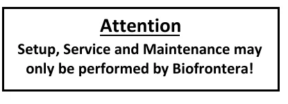
Figure 19: Servicing and maintenance may only be performed by Biofrontera
11 Maintenance and Cleaning
The device may under no circumstances be cleaned with aggressive cleaning agents or solvents (e.g. acetone or highly concentrated ethanol), as these promote wear and tear of the surface (paint coating) and labeling. Please use only a damp cloth when wiping over the labels.
Please avoid allowing any penetration of liquids into the lamp, as RhodoLED® XL-C is not waterproof and the electronics inside may be damaged. Do not maintain or clean the device while in use with patients.
Always unplug the lamp prior to cleaning and please observe the following cleaning practices:
Daily:
Wipe the plexiglass screen located on the bottom of the lamp head with a damp soft cloth (e.g., a microfiber cloth).
Weekly:
Wipe the entire lamp. Do not use a very wet or dripping cleaning cloth. The unit is not waterproof and damage could occur. Weekly cleaning can be carried out using a damp cloth, Multi-Purpose Cleaners (Clorox Healthcare VersaSure Wipes) or pre-soaked disinfection wipes based on quaternary ammonium compounds (e.g. Cavi wipes XL or Clorox disinfection wipes).
Please observe the following checks:
Monthly:
Check lamp for obvious visible damage such as damaged cables, worn off labeling, cracks on the lamp housing, etc.
Do not use a damaged device for treatment and please inform your supplier.
12 Disposal Instructions
Follow all local and governmental disposal laws and regulations when disposing of the RhodoLED® XL-C.
13 Technical Data
13.1 Electrical Connectors
Power supply unit:
Primary wide-range input 100-120 VAC
Secondary safety extra-low voltage output 48 VDC
Secondary standby voltage output 5 VDC
LED controller board:
Supply voltage input 48 VDC
2x CAN interface (2 pin)
LED board FFC (12 pin)
Distance sensor FFC (4 pin)
2 x connector ventilator (3 pin)
LED board:
LED controller board FFC 12 pin (3 x LED circuits, temperature)
Distance sensor FFC (4 pin)
Human Machine Interface (HMI) for operation:
Supply voltage input 48 VDC (2 pin)
Secondary standby voltage input 5 VDC (4 pin)
CAN interface (3 pin)
USB interface (5 pin, covered)
Speaker (2 pin)
Touch controller (4 pin)
Display data LVDS (40 pin)
On/off switch (2 pin)
HMI module to pillar external connector (10 pin)
Grounding (1 pin)
13.2 Specification
Type
RhodoLED® XL
Medical device class III; Device of protection class 1
Certification
UL certified E513735
Manual is valid for Software Version No.
g2.15.00.3911
Service interval
Biofrontera recommends performing service every 2 years
Number of LEDs
225
Typical peak wavelength
635 nm ± 5 nm
Light dose
Approx. 37 J/ cm2 at 4.9 inches (12.5 cm) distance, 10 min
Typical irradiance
approx. 60 mW/cm² ± 20 % at 4.9 inches (12.5 cm) distance
Max irradiance
approx. 72 mW/cm² at 4.9 inches (12.5 cm) distance
Illuminated area
An area of 9.06 x 11.42 inches (23 cm x 29 cm) is illuminated using all panels in curved shape.
Max. deviation of the intensity over the treatment area
Approx. 20 %
Treatment distance
4.9 ± 0.6 inches (12.5 cm ± 1.5 cm)
Measuring accuracy ± 0.3 cm (0.1 inches)
Transport conditions
Temperature: -4°F to +140°F (-20°C to +60°C)
Atmospheric pressure: 500 hPa - 1060 hPa
Relative humidity: 10% - 90%, non-condensing
Storage conditions
Temperature: +59°F to +95°F (+ 15°C to +35°C)
Atmospheric pressure: 500 hPa - 1060 hPa
Relative humidity: 10% - 90%, non-condensing
Maximum storage time 180 days
Operating conditions
Temperature: +59°F to +86°F (+15°C to + 30°C)
Atmospheric pressure: 500 hPa - 1060 hPa
Operational altitude: ≤ 4800 m above NN
Relative humidity: 10% - 90%, non-condensing.
RhodoLED® XL-C must be operated in environments of professional healthcare facilities.
Operating voltage
100-120 VAC, 60 Hz
Output voltage
48 VDC
Power consumption
In normal operation: approx. 750 VA
In standby mode: approx. 85 VA
Over-voltage category
II
Degree of contamination
2
Material group (CTI)
IIIb
Protection class
IP20
Size of the lamp
Height 5.76 ft (175.5 cm)
Width: 2.51 ft (76.4 cm)
Depth: 3.19 ft (97.1 cm)
Total lamp weight
165 lb. (75 kg)
For further information please directly contact Biofrontera.
14 Labeling and Symbols
14.1 Label on the Lamp Base
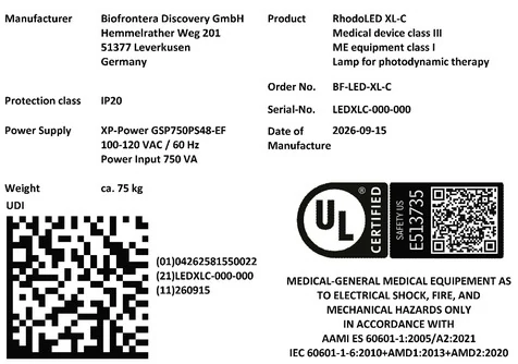
Figure 20: Product label (serial number and date of manufacturing vary) with UDI code of RhodoLED® XL-C on lamp base, individual code depends on the serial number and date of manufacturing of the device.
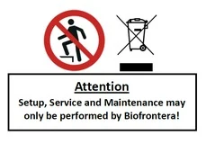
Figure 21: No stepping on the device, no disposal in household waste, information on setup and service.

Figure 22: Instruction for ground connector connection (not visible from the outside)
14.2 Label on LED Panels
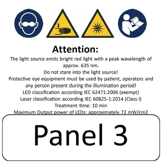
Figure 23: Instruction and notes on the LED panels
Figure 24: LED Panel numbering from Panel 1 to Panel 5
14.3 Description of Symbols
Symbol
Description
Eye protection is required.
Distance sensor of RhodoLED® XL-C is a class 1 laser product. A class 1 laser product is safe under all conditions of normal use.
IP20
IP (Ingress Protection):
Protection class of the housing against contact, foreign bodies and water
2 = against ingress of solid foreign bodies ≥ 12.5 mm Ø and larger
0 = Not protected against water

Technical and electric devices must not be disposed of with household waste. Please pay attention to the applicable disposal instructions found in the user manual.

Symbol for existing ground connector connections
Follow the instructions for use!
General warning signs:
Assembly and servicing may ONLY be performed by Biofrontera
Only transport lamp in the park position
Caution: heavy, do NOT lift alone.
Warning sign - risk of trapping fingers!
Bright light, do not stare into the light source

Do not step on the device.
15 Electromagnetic compatibility
RhodoLED® XL-C complies with the EMC requirements of IEC 60601-1-2:2014 + A1:2020. Other electrical devices can influence the device.
The use of accessories, transducers and cables other than those specified or provided by the manufacturer may result in increased electromagnetic emissions or reduced electromagnetic immunity of the equipment and may lead to incorrect operation. Assembly, service and repairs may only be performed by Biofrontera.
Guidelines and manufacturer's declaration - electromagnetic emissions
RhodoLED® XL-C is intended for operation in the electromagnetic environment detailed below.
The customer or operator of the device should ensure that it is operated in this environment.
The emission characteristics of RhodoLED® XL-C allow its use in industrial and hospital and healthcare professional environments (CISPR 11, Class A). When used in a residential environment (for which CISPR 11 normally requires Class B), this device may not provide adequate protection of radio services. The user may need to take corrective action by moving or repositioning the device.
Emission readings
Conformity
Electromagnetic environment - guidelines
HF emissions CISPR 11
Group 1
RhodoLED® XL-C only uses HF energy for its internal functionality. For this reason, its HF emission is very low and it is not likely that neighboring electronic devices would be disturbed.
HF emissions in accordance with CISPR 11
Class A
RhodoLED® XL-C is intended for operation in non-residential facilities and similar environments that are connected directly to a public low-voltage supply network that also supplies residential buildings.
Harmonics in accordance with IEC 61000-3-2
Class A
Voltage fluctuations/flickers in accordance with IEC 61000-3-3
In compliance
Guidelines and manufacturer's declaration - electromagnetic immunity
RhodoLED® XL-C is intended for operation in the electromagnetic environment detailed below. The customer or operator of the device should ensure that it is operated in this environment.
Immunity tests
IEC 60601 test levels
Compliance level
Electromagnetic environment - guidelines
Static discharge in accordance with IEC 61000-4-2
±8 kV contact discharge ±2 kV, ±4 kV, ±8 kV and ±15 kV air discharge
±8 kV contact discharge ±2 kV, ±4 kV, ±8 kV and ±15 kV air discharge
Floors should be made of wood or concrete or finished with ceramic tiles. If the floor is finished with synthetic material, the relative air humidity must be at least 30%.
Fast, transient electrical disturbances/bursts in accordance with IEC 61000-4-4
±2 kV for mains lines 100 kHz repetition frequency
±2 kV for mains lines
The quality of the supply voltage should correspond to that of a typical commercial or hospital environment.
Surges in accordance with IEC 61000-4-5
±1 kV voltage outer conductor - outer conductor ±2 kV outer conductor - earth
±1 kV voltage outer conductor - outer conductor ±2 kV outer conductor - earth
The quality of the supply voltage should correspond to that of a typical commercial or hospital environment.
Voltage dips, brief interruptions and fluctuations in the supply voltage in accordance with IEC 61000-4-11
0 % UT for 0.5 cycles at phase angles of 0°, 45°, 90°, 135°, 180°, 225°, 270° and 315° (applicable only to me equipment connected to single-phase a.c. mains)
0 % UT for 1 cycle
70 % UT for 25/30 cycles
0 % UT for 250/300 cycles
0 % UT for 0.5 cycles at phase angles of 0°, 45°, 90°, 135°, 180°, 225°, 270° and 315° (applicable only to me equipment connected to single-phase a.c. mains)
0 % UT for 1 cycle
70 % UT for 25/30 cycles
0 % UT for 250/300 cycles
The quality of the supply voltage should correspond to that of a typical commercial or hospital environment.
If the operator of the device needs functionality to be maintained despite interruptions in the energy supply, it is advisable to run the device on an uninterruptable power supply or a battery.
Power frequency (50/60 Hz) magnetic field in accordance with IEC 61000-4-8
30 A/m
30 A/m
Mains frequency magnetic fields should correspond to the values typically found in the commercial and hospital environment.
Comment: UT is the mains AC voltage prior to application of the test level
Guidelines and manufacturer's declaration - electromagnetic immunity
RhodoLED® XL-C is intended for operation in the electromagnetic environment detailed below. The customer or operator of the device should ensure that it is operated in this environment.
Immunity tests
IEC 60601 test levels
Compliance level
Electromagnetic environment - guidelines
Conducted HF disturbances
in accordance
with IEC 61000-4-6
3 V
150 kHz to 80 MHz
6 V
ISM bands 0.15 - 80 MHz
80 % AM with 1 kHz
3 V
6 V
Portable and mobile communication devices should not be used in closer proximity of the unit or its cables than the recommended safety distance of 300 mm.
Radiated HF disturbances
in accordance
with IEC 61000-4-3
3 V/m 80 MHz to 2.7 GHz
80 % AM with 1 kHz
3 V/m
Interference may occur in the vicinity of equipment marked with the following symbol.

Comment 1: These guidelines may not be applicable in all cases. The propagation of electromagnetic values is influenced by absorptions and reflections of buildings, objects, and people.
Recommended safety distances between portable and mobile HF telecommunication devices and the RhodoLED® XL-C.
Portable RF communications equipment (radios, including their accessories such as antenna cables and external antennas) should not be used at a distance less than 30 cm (or 12 inches) from the manufacturer's specified parts and leads of the RhodoLED® XL-C. Failure to do so may result in a reduction in the performance of the device.
RhodoLED® XL-C should not be used directly alongside or between other electrical equipment.
Guidelines and manufacturer’s declaration – proximity fields from RF wireless communication equipment
RhodoLED® XL-C is intended for operation in the electromagnetic environment detailed below. The customer or operator of the device should ensure that it is operated in this environment.
Service
Frequency range/ discrete frequencies MHz
Compliance level
[V/m]
TETRA 400
385
27
GMRS 460, FRS 460
450
29
LTE Band 13, 17
710
745
780
9
GSM 800/900, TETRA 800,
iDEN 820, CDMA,
LTE Band 5
810
870
930
28
GSM 1800, CDMA 1900,
GSM 1900,DECT,
LTE Band 1,3,4, 25
1720
1845
1970
28
Bluetooth, WLAN, 802.11 b/g/n, RFID 2450, LTE Band 7
2450
28
WLAN 802.11
a/n
5240
5500
5785
9
Version 2.0 SW_G2